Position detector for a scanning device

a scanning device and position detector technology, applied in the direction of converting sensor output, instruments, electric discharge lamps, etc., can solve the problems of low exact position of beam trajectory, low angular resolution of position detectors, and large drift, etc., to achieve the effect of higher accuracy, easy and precise realization, and the same coverag

Inactive Publication Date: 2005-07-26
SCANLAB GMBH
View PDF8 Cites 39 Cited by
  • Summary
  • Abstract
  • Description
  • Claims
  • Application Information

AI Technical Summary

Benefits of technology

[0019]The rotatable arrangement of the light blocker can be constructionally achieved in a simple way by means of a shaft, which can in comparison to a translational motion of the light source be realized more easily and precisely. By the shape of a section of an annulus of the light detectors a measuring signal can be achieved, which is linear with respect to the angular position of the light blocker. The respective light detector's shape of a section of an annulus can be achieved e.g. by the use of a light sensitive element having the shape of a section of an annulus as the light detector. However, the light detector advantageously comprises any light sensitive element, e.g. a conventional circular or rectangular photodiode, which is provided with a mask comprising a recess having the shape of a section of an annulus. Herewith, a light detector of the shape of a section of an annulus is achieved in an especially inexpensive way. Preferably, the respective light detector comprises a light sensitive element, wherein a common mask is provided for at least several of the light detectors, which mask is provided with a corresponding number of recesses having the shape of a section of an annulus, whereby the corresponding light detector's shape of a section of an annulus is formed. Particularly preferably only a single mask is provided, with a number of recesses therein, each having the shape of a section of an annulus, which number corresponds to the number of light detectors. By this the detector surfaces are mutually adjusted with an higher accuracy.
[0020]According to a preferred embodiment at least four light detectors are provided, which are arranged around the rotational axis of the rotatably arranged light blocker such that respectively two light detectors which are arranged diametrically opposite to each other experience essentially the same coverage by the light blocker. With such a light detector arrangement, an unwanted variation of the radial position of the light blocker can be detected and compensated in a simple fashion, since the light detectors being arranged in a mutually diametrical fashion with respect to the rotational axis of the light blocker experience the same amount of change regarding the covered surfaces. In the case that more than four light detectors are provided their number also corresponds to an even number. With more than four light detectors, thus e.g. with six or eight light detectors, a higher signal yield is achieved, so that the detector signals need to be amplified only slightly, by which a fast signal processing and thus a faster operating detector can be realized.
[0021]According to an embodiment of the invention respectively two adjacent light detectors are formed as a slit diode, such that the overall light detector arrangement can be realized in an inexpensive and space-saving way.

Problems solved by technology

However, the fabrication of such detectors is relatively costly and thus expensive.
However, such optical position detectors had a lower angular resolution and a larger drift as compared to capacitive position detectors, so that they were used only in applications in which the demands on the exact position of the beam trajectory are not very high (e.g., laser shows).

Method used


Image

  • Position detector for a scanning device
  • Position detector for a scanning device
  • Position detector for a scanning device

Examples


Embodiment Construction

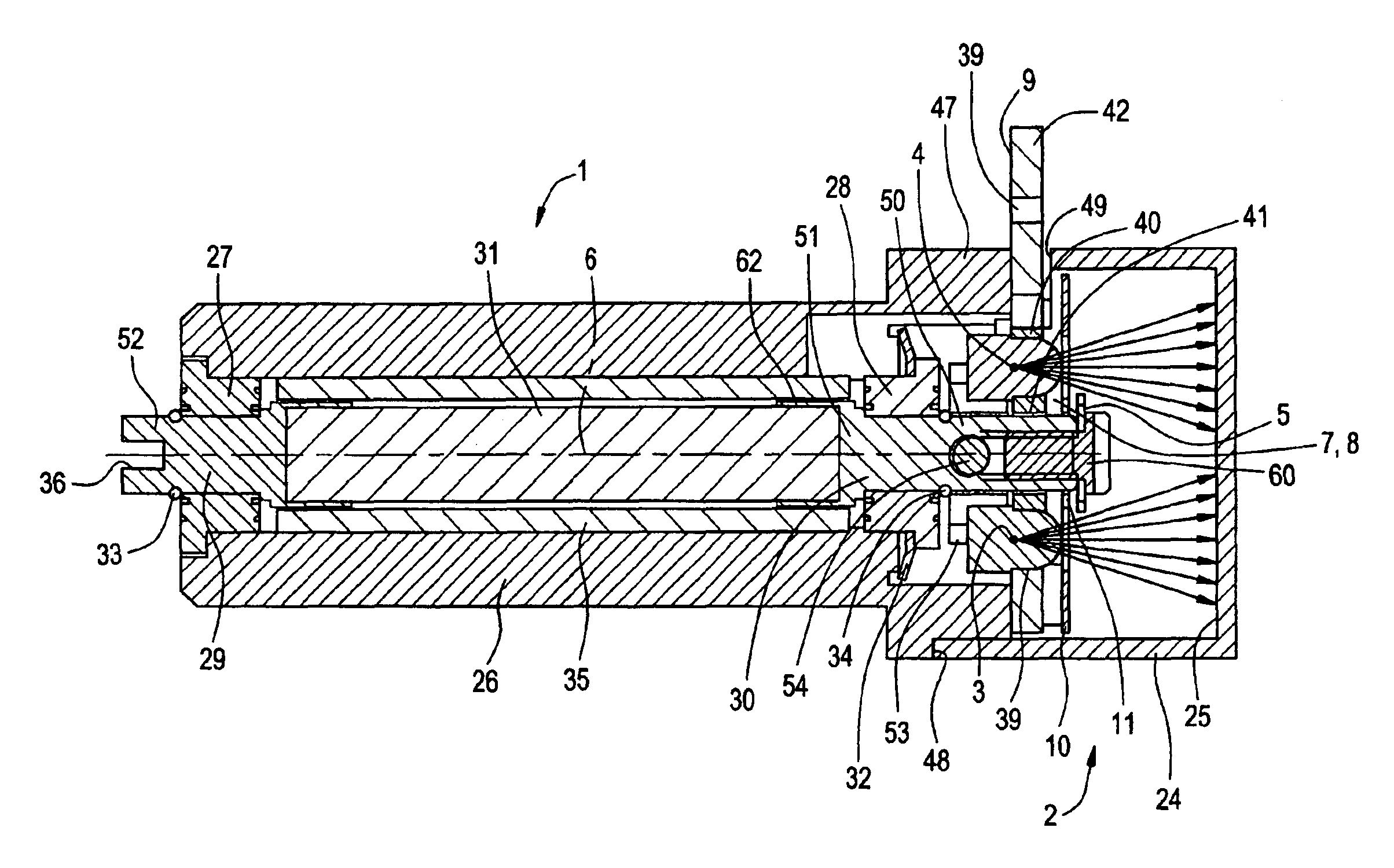
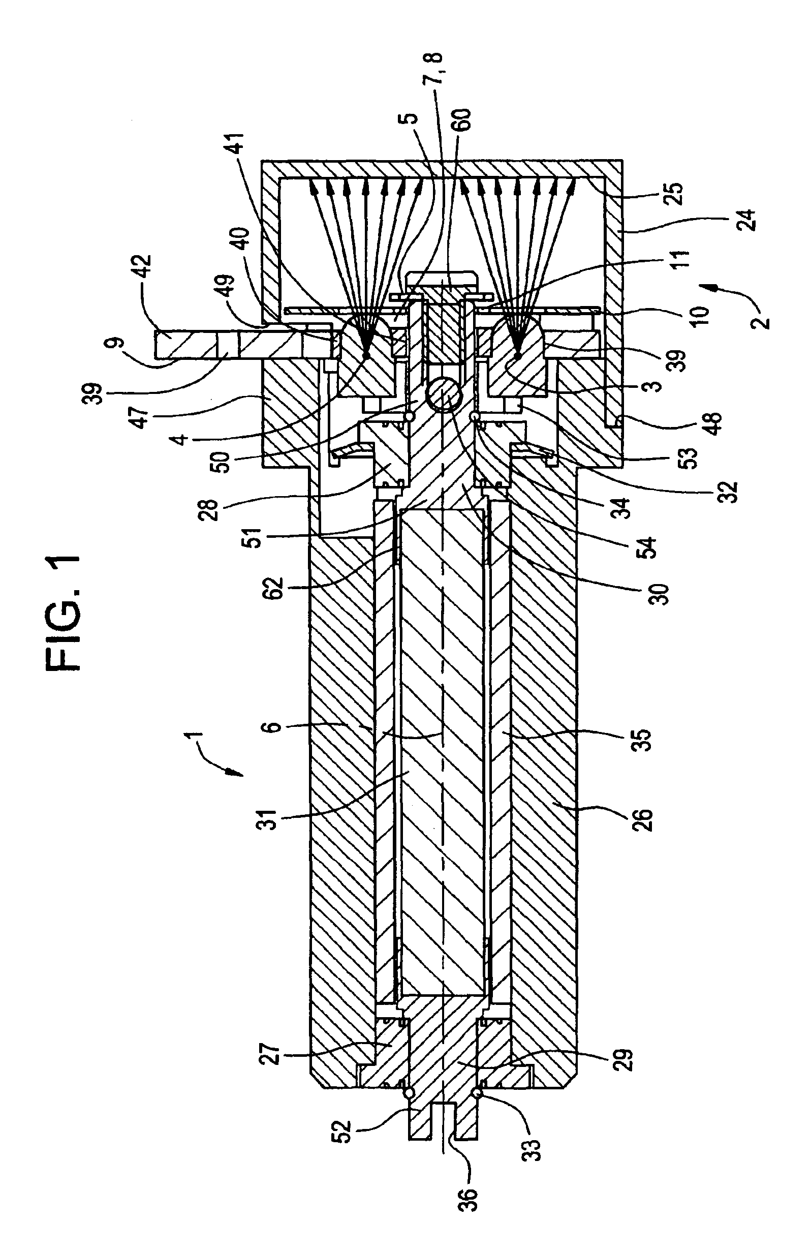
[0029]As is shown in FIG. 1 and FIG. 2, a scanning device 1 according to the present invention comprises a position detector 2 being arranged at its front side. The position detector 2 is constituted as an optical position detector. The optical position detector 2 comprises two light sources 3, 4 being located behind a light blocker 5, which in turn is tightly connected to a rotationally arranged shaft 6 extending backwards between the two light sources 3, 4. Thus the light blocker 5 is rotated along with the rotation of the shaft 6. The light sources 3, 4 are arranged symmetrically with respect to the longitudinal axis of the shaft 6. Preferably, a light emitting diode (LED) is used as the respective light source 3, 4; however, other lamps are possible as well.

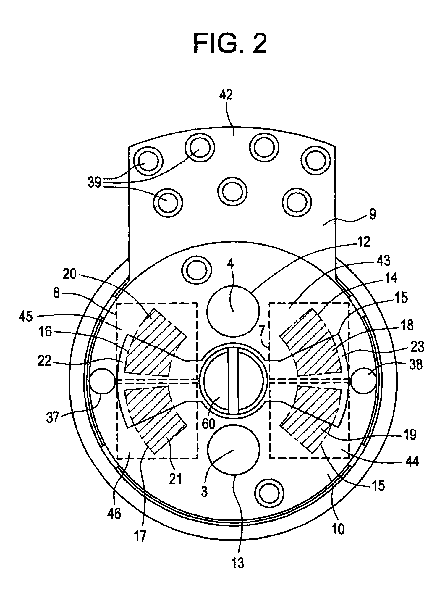
[0030]Directly laterally beside the light sources 3, 4, a detector arrangement comprising four light detectors 18, 19, 20, 21 is located in a plane extending vertically to the longitudinal axis of the shaft 6. These four ligh...


PUM


Abstract

A position detector for a scanning device includes a movable light blocker, at least two light detectors which are located behind the light blocker and which can be covered by the light blocker at different extents of coverage as the light blocker is being moved, so that the position of the light blocker can be determined, and at least one light source for emitting light onto the light detectors. A reflector is provided which is located in front of the light blocker. The light source is arranged such that the light emitted therefrom is emitted onto the reflector. Furthermore, the reflector is arranged such that the light impinging thereon is reflected onto the light detectors.

Description

CROSS REFERENCE TO RELATED APPLICATIONS[0001]This is a U.S. National Phase Application under 35 U.S.C. § 371 and applicant herewith claims the benefit of priority of PCT / EP00 / 05528 filed Jun. 15, 2000, which was published Under PCT Article 21(2) in English, the entire contents of which are incorporated herein by reference.FIELD OF THE INVENTION[0002]The present invention relates to a position detector, in particular to an optical position detector, for a scanning device and to a scanning device comprising the position detector according to the present invention.BACKGROUND OF THE INVENTION[0003]Nowadays, precise determining of spatial positions is, in particular due to an increasing extent of automatisation in fabrication and processing methods, an important prerequisite for an efficient fabrication and processing of low tolerance structural members. A precise control of the beam trajectory of intense laser light is required for e.g. in laser beam material processing. Optical scanner...

Claims


Application Information

Patent Timeline
Patent Type & Authority Patents(United States)
IPC IPC(8): G01D5/347G01D5/26G01B11/00
CPCG01D5/34715G01D5/3473
Inventor PETSCHIK, NORBERTBURKHARDT, FRANK
Owner SCANLAB GMBH
Why Eureka
Try Eureka