Method and apparatus for reducing noise and vibration in switched reluctance motor drives

a technology of switched reluctance motors and noise reduction methods, applied in the direction of motor/generator/converter stoppers, dynamo-electric converter control, instruments, etc., can solve the problems of high vibration and acoustic noise of srm drives, and achieve the effect of reducing noise and vibration

Inactive Publication Date: 2005-07-26
TEXAS A&M UNIVERSITY
View PDF8 Cites 36 Cited by
  • Summary
  • Abstract
  • Description
  • Claims
  • Application Information

AI Technical Summary

Benefits of technology

[0004]According to one embodiment of the present invention, a method of reducing noise and vibration in a switched reluctance motor drive is provided. The method includes generating, by a computer, a phase current profile; generating a phase current according to the phase current profile; and applying the phase current to the switched reluctance motor drive. Generating the phase current profile includes initializing one or more first profile parameters that define at least a first portion of the phase current profile. Generating the phase current profile also includes determining whether a first performance criterion is satisfied based on operation of the switched reluctance motor drive using the first profile parameters. Generating the phase current profile also includes updating at least one the first profile parameters if the first performance criterion is not satisfied.

Problems solved by technology

However, SRM drives generally produce high levels of vibration and acoustic noise, which are particularly problematic in introducing SRM technology into domestic applications.

Method used


Image

  • Method and apparatus for reducing noise and vibration in switched reluctance motor drives
  • Method and apparatus for reducing noise and vibration in switched reluctance motor drives
  • Method and apparatus for reducing noise and vibration in switched reluctance motor drives

Examples


Embodiment Construction

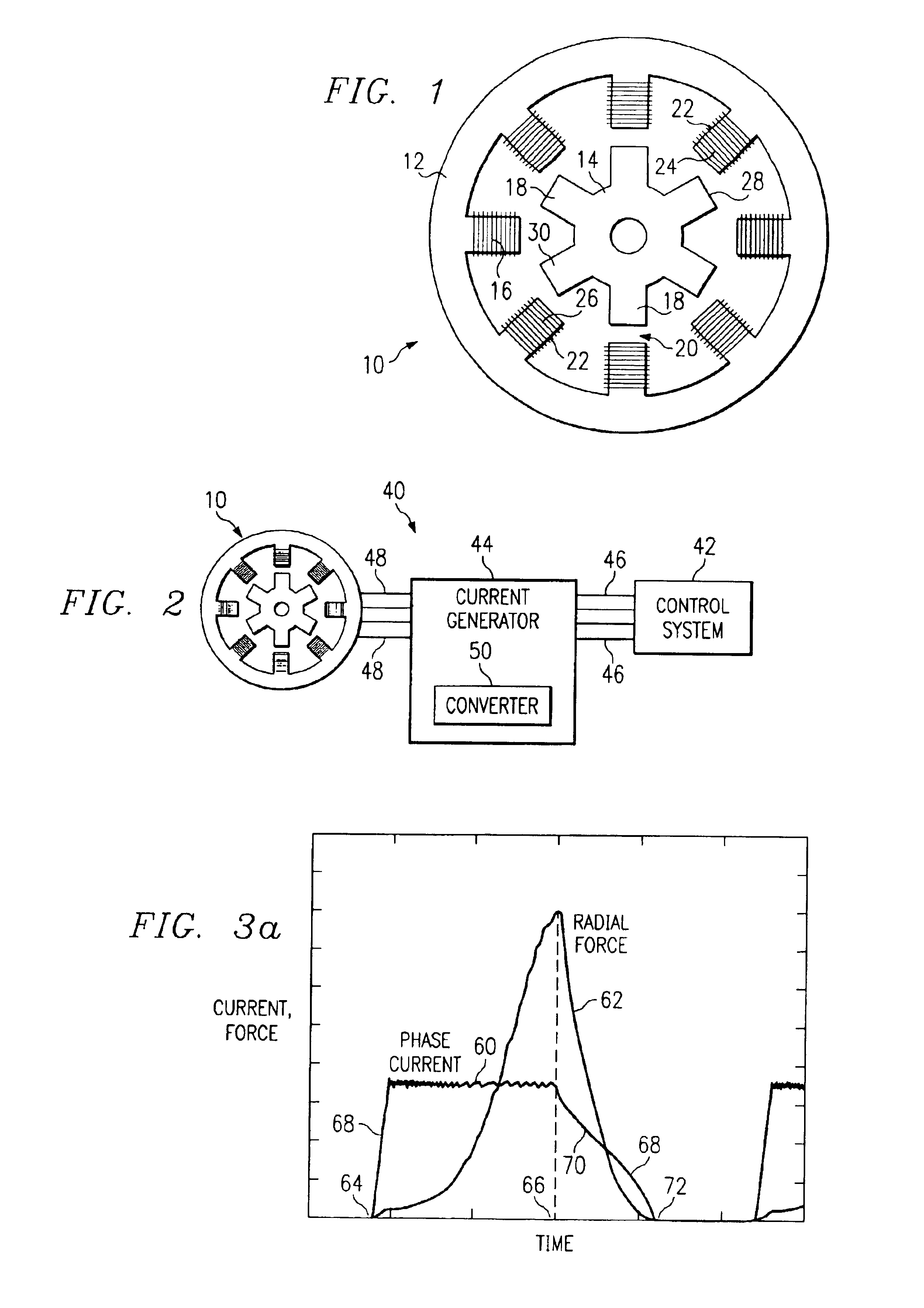
[0021]FIG. 1 illustrates a cross-sectional view of switched reluctance motor 10. Switched reluctance motor 10 includes a stator 12 and a rotor 14 that rotates inside stator 12. Stator 12 includes a plurality of stator poles 16 and rotor 14 includes a plurality of rotor poles 18. As rotor 14 rotates, airgaps 20 separate stator poles 16 from rotor poles 18. Switched reluctance motor 10 shown in FIG. 1 is referred to as an 8 / 6 SRM since stator 12 includes eight stator poles 16 and rotor 14 includes six rotor poles 18. Other configurations of switched reluctance motors, including a 6 / 4 SRM, are also commonly used and may benefit from the teachings of the invention.

[0022]A winding 22, for example a copper winding, is wound around each stator pole 16. Windings 22 on diametrically opposite pairs of stator poles 16, such as the pair shown as stator poles 24 and 26, are connected in series. Phase currents are sent through windings 22 on pairs of stator poles 16 connected in series, such as s...


PUM


Abstract

According to one embodiment of the invention, a method includes generating, by a computer, a phase current profile, generating a phase current according to the phase current profile, and applying the phase current to the switched reluctance motor drive. Generating the phase current profile includes initializing one or more first profile parameters which define at least a first portion of the phase current profile. Generating the phase current profile also includes determining whether a first performance criterion is satisfied based on operation of the switched reluctance motor drive using the first profile parameters. Generating the phase current profile also includes updating at least one the first profile parameters if the first performance criterion is not satisfied.

Description

RELATED APPLICATIONS[0001]This patent application claims the benefit under 35 U.S.C. § 119(e) to U.S. provisional patent application U.S. Ser. No. 60 / 250,022 filed Nov. 30, 2000, and entitled Method and Apparatus for Reducing Noise and Vibration in Switched Reluctance Motor Drives.TECHNICAL FIELD OF THE INVENTION[0002]This invention relates in general to switched reluctance motors and, more particularly, to a method and apparatus for reducing noise and vibration in switched reluctance motor drives.BACKGROUND OF THE INVENTION[0003]Switched reluctance motor (SRM) drives have attracted renewed interest recently due to advancements in power electronic devices, high-speed microcontrollers and advanced control strategies. Positive aspects of SRM drives include their inherent variable speed capability, simple construction, robust performance, and low manufacturing cost. However, SRM drives generally produce high levels of vibration and acoustic noise, which are particularly problematic in ...

Claims


Application Information

Patent Timeline
Patent Type & Authority Patents(United States)
IPC IPC(8): H02P1/46H02P1/16H02P3/18H02P25/08
CPCH02P25/088H02P25/098
Inventor EHSANI, MEHRDADFAHIMI, BABAK
Owner TEXAS A&M UNIVERSITY
Why Eureka
Try Eureka