
Electric field sensor

a sensor and electric field technology, applied in the field of electric field sensors, can solve the problems of low power, low cost, long life, no presently known or readily apparent masking or countermeasure techniques or devices available for masking or concealing e-field distortions or frustrating sensor detection of e-field distortions, etc., and achieves low power, long life, and low cost.

Inactive Publication Date: 2005-07-26
BAE SYST INFORMATION & ELECTRONICS SYST INTERGRATION INC
View PDF41 Cites 78 Cited by
  • Summary
  • Abstract
  • Description
  • Claims
  • Application Information

AI Technical Summary

Benefits of technology

[0023]Embodiments of the present invention are included herein, wherein the present invention is designed in contemplation of the deficiencies of the prior art. The present invention is an E-field detector system including at least one E-field distortion sensor that can detect distortion of the E-field by a person, vehicle, weapon, or electric power source. The present invention compensates for background noise in the E-field by using coherent signal processing to isolate the detected source from the background noise and thus enable correlation of the distortion source with its electrostatic signature. It is low cost, passive, low power, long life, and extremely small. The detection spectrum includes the E field from sub 1 Hz to greater than 1 MHz.
[0024]As the E field travels at the speed of light, the measurements can alert to various dangerous conditions. There is little if any attenuation because of dust or smoke, which can affect other sensor types. And, while the deficiencies in audio and visual sensors are well Known, the present invention provides a completely different set of data. In addition, combining the E field sensors with other sensor type results in a superior detection capability that can function in almost any environment.

Problems solved by technology

It is low cost, passive, low power, long life, and extremely small.
However, unlike visual, infra-red, audio, and other spectra detected using prior art sensors, there are no presently known or readily apparent masking or countermeasure techniques or devices available for masking or concealing E-field distortions or for frustrating sensor detection of E-field distortions.

Method used


Image

  • Electric field sensor
  • Electric field sensor
  • Electric field sensor

Examples


Embodiment Construction

[0054]To those skilled in the art, the invention admits of many variations. The following is a description of a preferred embodiment, offered as illustrative of the invention but not restrictive of the scope of the invention. Electro static event (ESE) sensors and systems according to the present invention exploit unintended and unavoidable electrostatic emissions in the spectrum from sub 1 Hz to greater than 1 MHz. The sensors are passive, low cost, small, low power and examine unintended or unavoidable emissions.

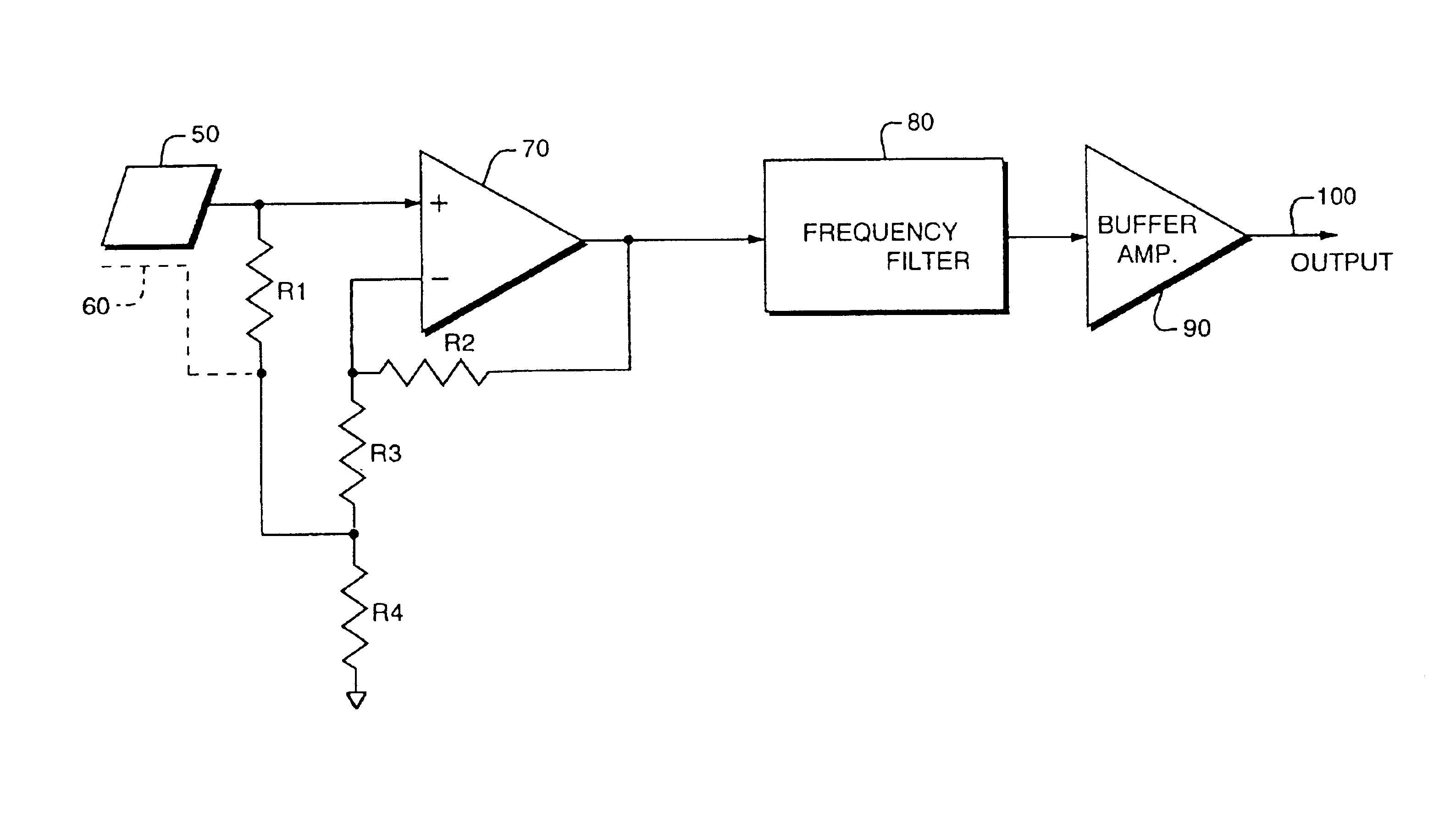
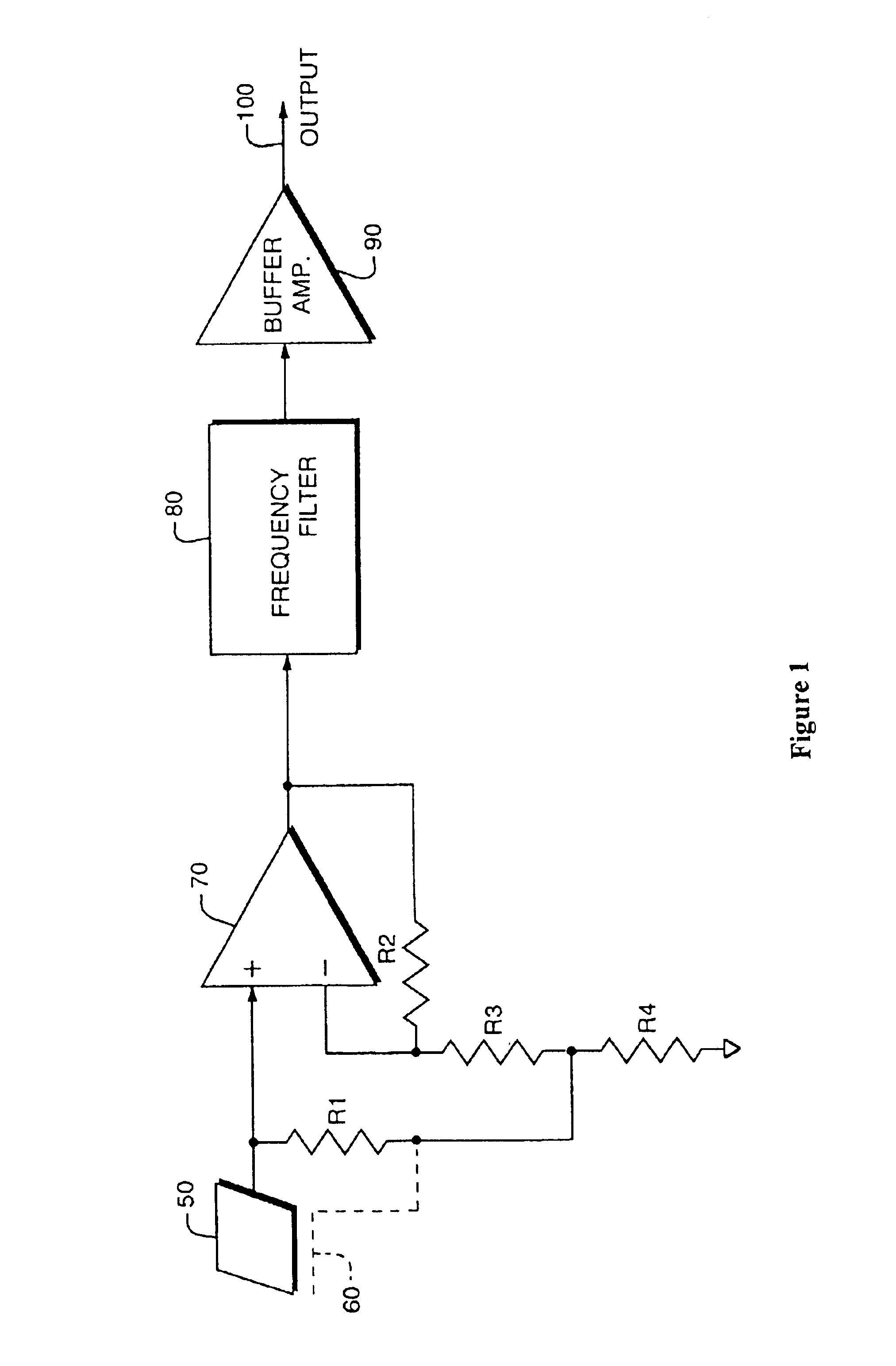
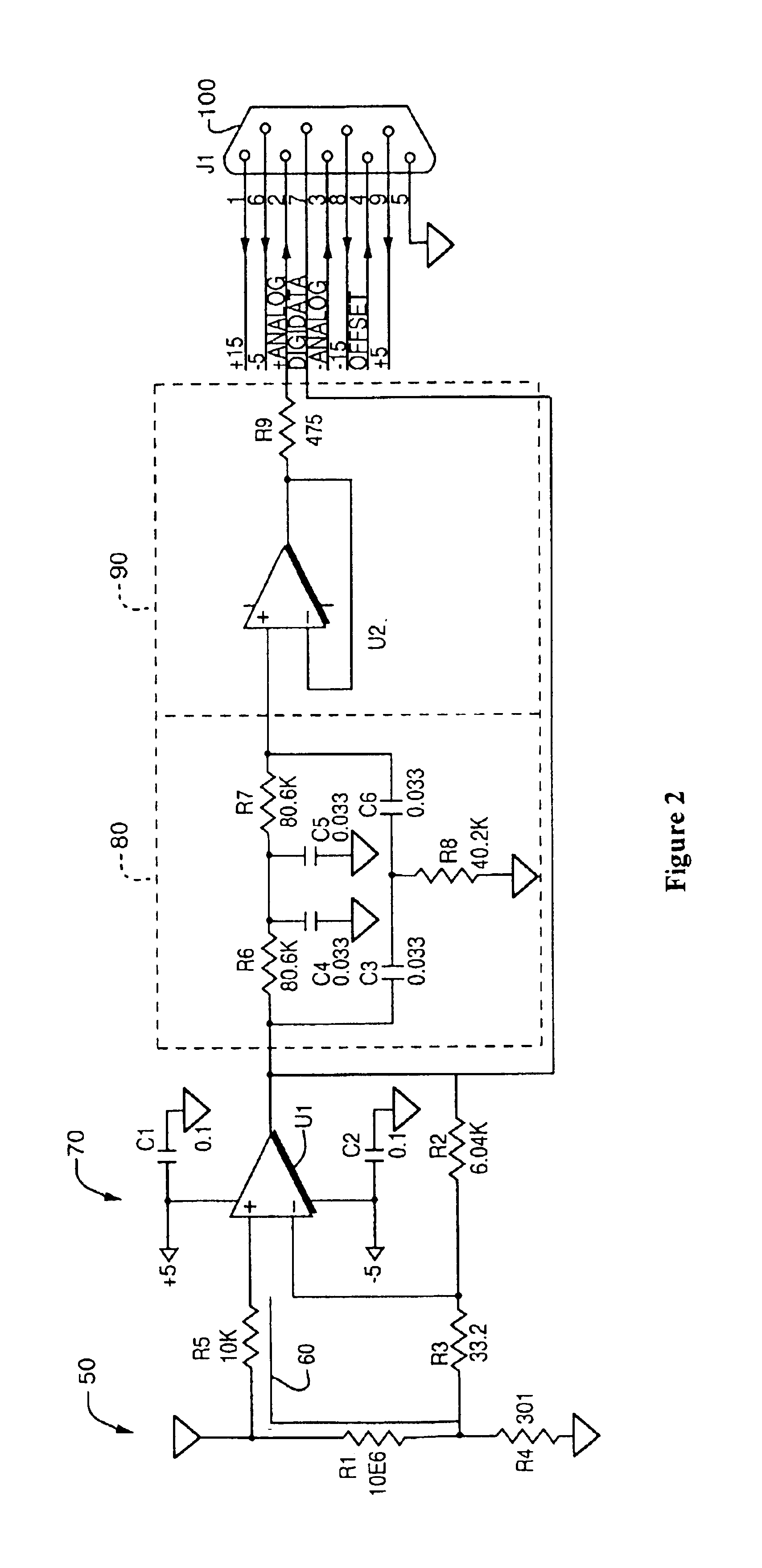
[0055]FIG. 1 is a block diagram representing a simple embodiment of the present invention sensor for detecting E-field distortions illustrating the circuit arrangement as well as the interconnection of the inputs and outputs. The sensing area 50 or “antenna” is generally a small receptive element, and in a preferred embodiment the sensing area 50 is a printed wiring board (PWB) etch or pad although it could also be an external sphere or other receptive unit.

[0056]The senso...


PUM


Abstract

The invention is a detection system and in one embodiment uses inexpensive, miniaturized sensors for detecting electric field (E-field) disturbances. Such sensors are easily and covertly deployable and have low power consumption. The devices may incorporate visual or audio alerts and can include communications hardware for transmitting data for further processing of the electrostatic events.

Description

RELATED APPLICATIONS[0001]This application claims the benefit of U.S. Provisional Applications No. 60 / 340,176, filed Dec. 10, 2001, and No. 60 / 356,557, filed Feb. 12, 2002. In addition, this application is a continuation-in-part of U.S. application Ser. No. 10 / 256,812, filed Sep. 27, 2002. Each of these applications is herein incorporated in its entirety by reference.FIELD OF THE INVENTION[0002]This invention relates to electrostatic sensors and to detecting, discriminating, and identifying electrostatic signatures caused by unintentionally created and naturally occurring electrostatic fields.BACKGROUND OF THE INVENTION[0003]Changes in the Electric-field (E-Field) are often unintended and unavoidable electrostatic emissions in the spectrum from sub 1 Hz to greater than 1 MHz. E-field distortions are caused by the spatial imbalance of electric charges. The electric field distortions in one instance are the result of a charge imbalance while others result from the distortion of the na...

Claims


Application Information

Patent Timeline
Patent Type & Authority Patents(United States)
IPC IPC(8): G01D9/00G01R29/08G01R31/00
CPCG01D9/005G01R29/0878G01R29/12G01R15/165G01R29/24G01V3/088
Inventor ZANK, PAUL A.SUTPHIN, ELDON M.BUCHANAN, DAVID W.CEHELNIK, THOMAS G.
Owner BAE SYST INFORMATION & ELECTRONICS SYST INTERGRATION INC
Learn More