Surface mount coil with edgewise winding

a surface mount coil and coil technology, applied in the direction of inductances, inductances with magnetic cores, basic electric elements, etc., can solve the problems of increased production costs, cost increase, cost increase, etc., and achieve the effect of improving reliability and high reliability

Inactive Publication Date: 2005-07-26
MINEBEA CO LTD
View PDF7 Cites 76 Cited by
  • Summary
  • Abstract
  • Description
  • Claims
  • Application Information

AI Technical Summary

Benefits of technology

[0021]In this configuration, since the rectangular insulated wire as the electrodes is tightly fixed on at least one notch formed on the base flange, the edgewise wound coil can be securely fixed to the base flange. Also, since the starting and finishing ends of the edgewise wound coil are provided with solder and the electrodes each having a large area for soldering are fixed with adhesive, defects such as shakiness, liftoff, connection failure, and wire breakage can be cut down as well as miniaturization, low-profile, and a high reliability for supplying a large current can be achieved. Further, since the plastic covering case is securely engaged with the base flange by means of the hooks, and since the plastic covering case presses elastically against the flanged spool, the coil can be fixed easily and securely to the base flange during manufacture of the coil, thereby improving its reliability.

Problems solved by technology

In the type where the both ends of the round insulated wire are bound around and connected to the connecting terminals of the plate-like metallic lead frames, its production cost is increased because the lead frames (the electrodes) have to be discretely provided, and an additional operation process is required for fitting the lead frames thus involving a cost increase.
In the type where the lead terminals are provided on the insulating board made of resin, and winding ends are connected to the coated portion thereby constituting electrodes, a cost increase is involved due to additional materials, specifically the electrode materials, and also due to an additional operation process for coating and baking the electrode materials.
The type, where winding ends are bound around and soldered to the flange of the drum core thereby constituting electrodes, has a limited allowable value of current and therefore cannot be used in a heavy-current circuit, and also often incurs shakiness when mounted on a printed circuit board.
Furthermore, although another type coil, where the rectangular insulated wire is wound edgewise, is superior to the coil using the round insulated wire in reduction in profile, number of parts, manufacturing operation, and allowable value of current, it has the following reliability problems.
Specifically, this type coil suffers a decreased soldered area of the winding ends constituting electrodes due to the soldered portion peeling off from the core or plastic board and flatness shakes and is lifted off when mounted on a printed circuit board.

Method used


Image

  • Surface mount coil with edgewise winding
  • Surface mount coil with edgewise winding
  • Surface mount coil with edgewise winding

Examples


Embodiment Construction

[0036]Preferred embodiments of the present invention will be described hereinafter with reference to the accompanying drawings.

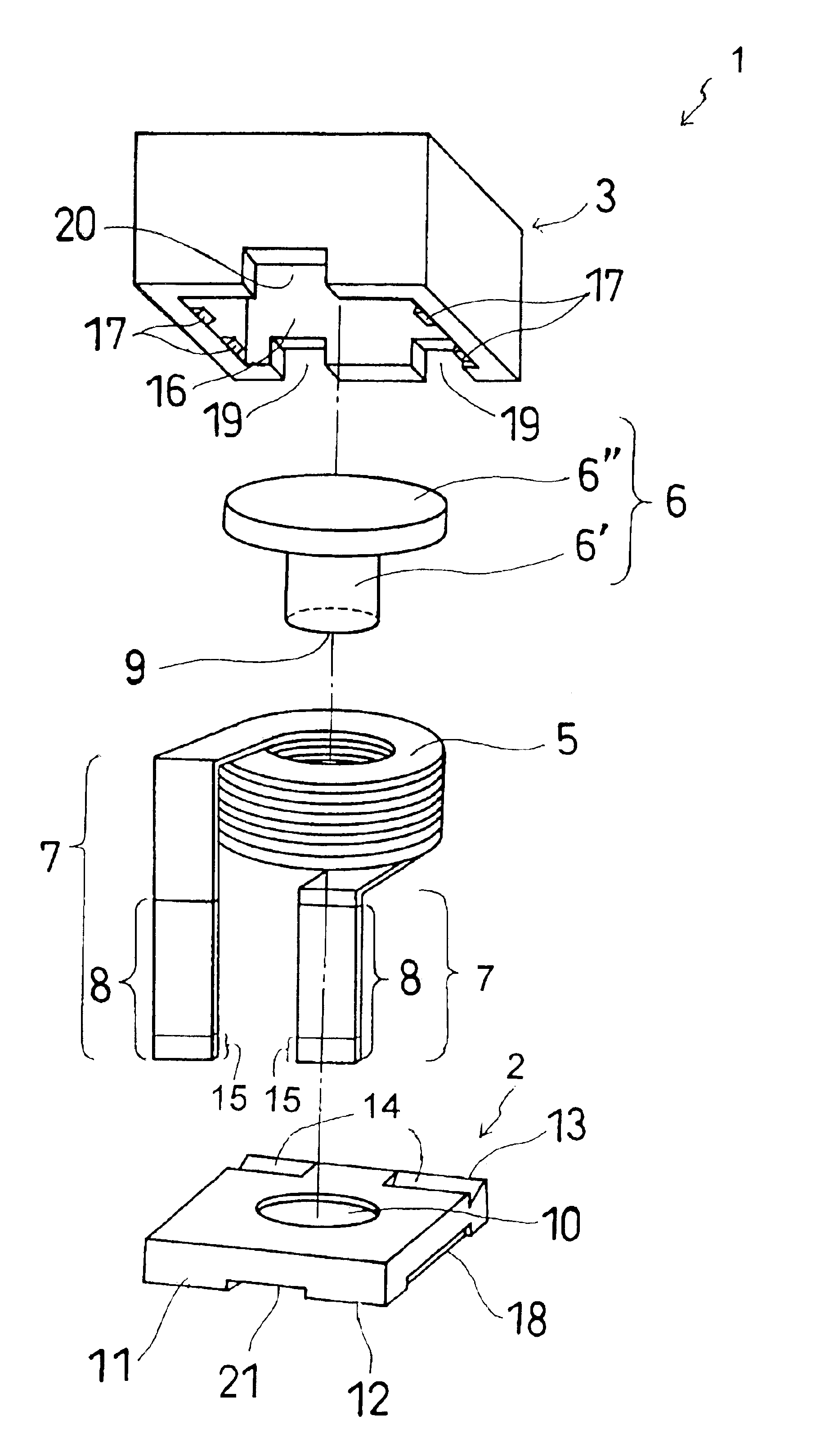
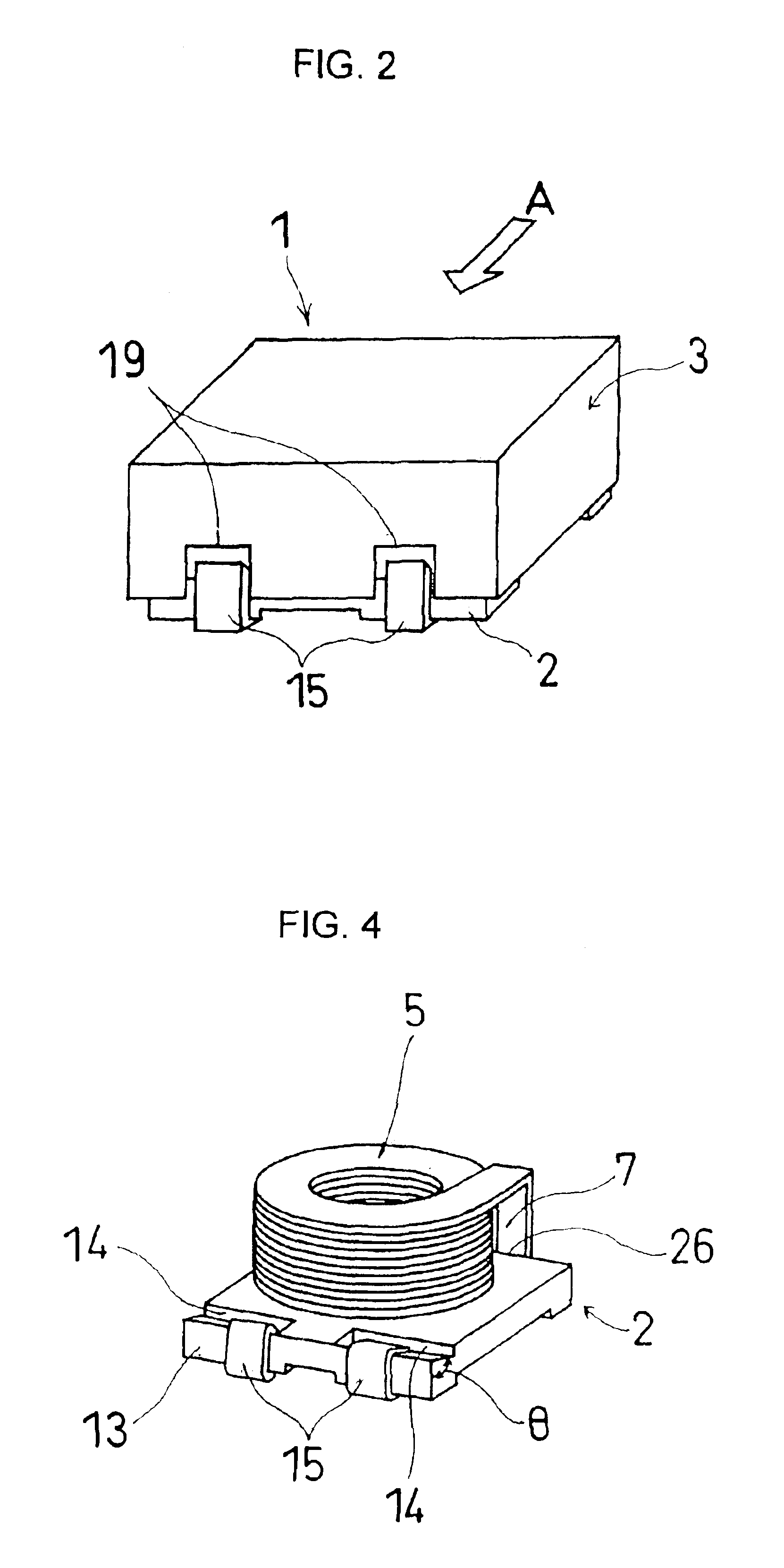
[0037]Referring to FIG. 2, a surface mount coil 1 is substantially a rectangular parallelepiped and is structured such that a substantially rectangular base flange 2 is covered with a plastic covering case 3 placed therein. As will hereinafter be detailed, electrodes have electrode fixation portions 15 which have their distal ends hooked to be fixedly attached to the base flange 2.

[0038]Referring to FIG. 3, the surface mount coil 1 is viewed from a direction shown by an arrow A in FIG. 2. The surface mount coil 1 is generally composed of: an edgewise wound coil 5 made of a rectangular wire; a flanged spool 6 including a spool section 6′ to be inserted in the edgewise wound coil 5 and a flange section 6″ integrally connected to one end of the spool section 6″; the aforementioned base flange 2 which is substantially rectangular and to which the other end 9 of ...


PUM

PropertyMeasurementUnit
thicknessaaaaaaaaaa
angleaaaaaaaaaa
thicknessaaaaaaaaaa

Abstract

A surface mount coil comprises: a flanged spool, which includes a spool section and a flange section integrally connected with one end of the spool section; a base flange, which is shaped substantially rectangular and fixedly connected to the other end of the spool section; and an edgewise wound coil, which is made of a rectangular insulated wire, and which is structured such that starting and finishing ends of the rectangular insulated wire lead out in parallel with each other around the base flange in such a manner as to extend along and on one side surface, a bottom surface, and another side surface opposite to the one side surface, and are fixed at an edge of a top surface of the base flange.

Description

BACKGROUND OF THE INVENTION[0001]1. Field of the Invention[0002]The present invention relates to a surface mount coil using a drum core.[0003]2. Description of the Related Art[0004]A conventional surface mount coil using a drum core has been extensively used and is constructed such that, as shown in FIG. 1, a round insulated wire is wound around a spool portion 53 of a drum core 50 which is integrated with a top flange 51 and a base flange 52 so as to constitute a drum core 50 and both ends of the round insulated wire is connected to respective connecting terminals of plate-like metallic lead frames 55 and 55. The plate-like metallic lead frames 55 and 55 are adhesively fixed to the drum core thereby constituting a pair of terminal electrodes of the coil. The electrodes have been conventionally called “lead frame type electrodes”. In addition, although not shown, there are other types structured such that lead terminals are provided on an insulating board made of resin and adapted f...

Claims


Application Information

Patent Timeline
Patent Type & Authority Patents(United States)
IPC IPC(8): H01F27/29H01F27/02H01F17/04H01F27/28H01F27/30
CPCH01F27/027H01F27/292H01F2017/046
Inventor OKAMOTO, TOSHINORI
Owner MINEBEA CO LTD
Why Eureka
Try Eureka