Safety detection and protection system for power tools

a protection system and power tool technology, applied in the field of power tools, can solve the problems of unwieldy users, system complexity, and high cost, and achieve the effect of rapid stopping of the saw blad

Inactive Publication Date: 2005-07-26
CREDO TECH CORP +1
View PDF46 Cites 209 Cited by
  • Summary
  • Abstract
  • Description
  • Claims
  • Application Information

AI Technical Summary

Benefits of technology

[0005]The present invention comprises a detection system for detecting a dangerous condition for an operator using a power tool of the type which has an exposed blade relative to a work surface and a protection system for minimizing, if not eliminating the possibility of a user being injured by contacting the blade. In one preferred embodiment of the present invention, a proximity detection system is capable of detecting the presence of a user near the blade of a table saw and a protection system that can either retract the blade below the work surface of the table saw or terminate the drive torque to the blade which can result in rapid stopping of the saw blade by a workpiece that is being cut.
[0006]Several embodiments of the present invention are capable of sensing a plurality of spatial volumes adjacent the blade and measure the dielectric characteristic of each of the volumes and over time determine the existence, direction and speed of movement of human tissue in each of x, y and z directions to thereby determine if a dangerous condition exists. Moreover, such embodiments can determine the severity of the dangerous condition and the protective response that should be taken as a function of the severity of the condition.
[0007]A preferred embodiment utilizes a blade retraction mechanism that will rapidly pull the blade below the work surface of the table saw when actuated by a pyrotechnic device that has a firing time that is sufficiently fast to prevent injury to a user's hand in the vast majority of realistic operating scenarios.

Problems solved by technology

This is particularly true with regard to power tools of the type which have relatively large exposed moving blades that can easily cause serious injury to individuals who carelessly use the tool or who are the victim of a true accident that results from unforeseen conditions.
While safety systems have been developed for machine tools and other commercial tools, such as stamping tools, punch presses and other machines which exert great force in manufacturing metal and other parts, such systems often have a level of sophistication and complexity that is achieved only at a cost that is prohibitive if considered for use in tools that are marketed to individual consumers or small contractors and tradesmen.
More particularly, the well known table saw that is used by woodworkers and tradesmen has a rotating blade that is often exposed during use even though blade guards have been provided with such table saws when sold for the last several decades.
Such blade guards, while effective to prevent some injuries, are considered unwieldy by many users.
In fact, many users find that such blade guards actually interfere with the use of the table saws and therefore remove such blade guards most of the time.
Obviously, a rotating table saw blade can cause great injury to a user and countless hand injuries occur annually because of careless use or the occurrence of fortuitous accidents.
Because such solenoid operated systems are generally slow acting, they have been unable to prevent injury in many operating scenarios.
All of these systems have one or more disadvantages in terms of cost, convenience of use, early and effective detection of a dangerous condition and the ability to provide graduated protective actions as a function of the characteristics that develop during a potentially dangerous condition.

Method used


Image

  • Safety detection and protection system for power tools
  • Safety detection and protection system for power tools
  • Safety detection and protection system for power tools

Examples


first embodiment

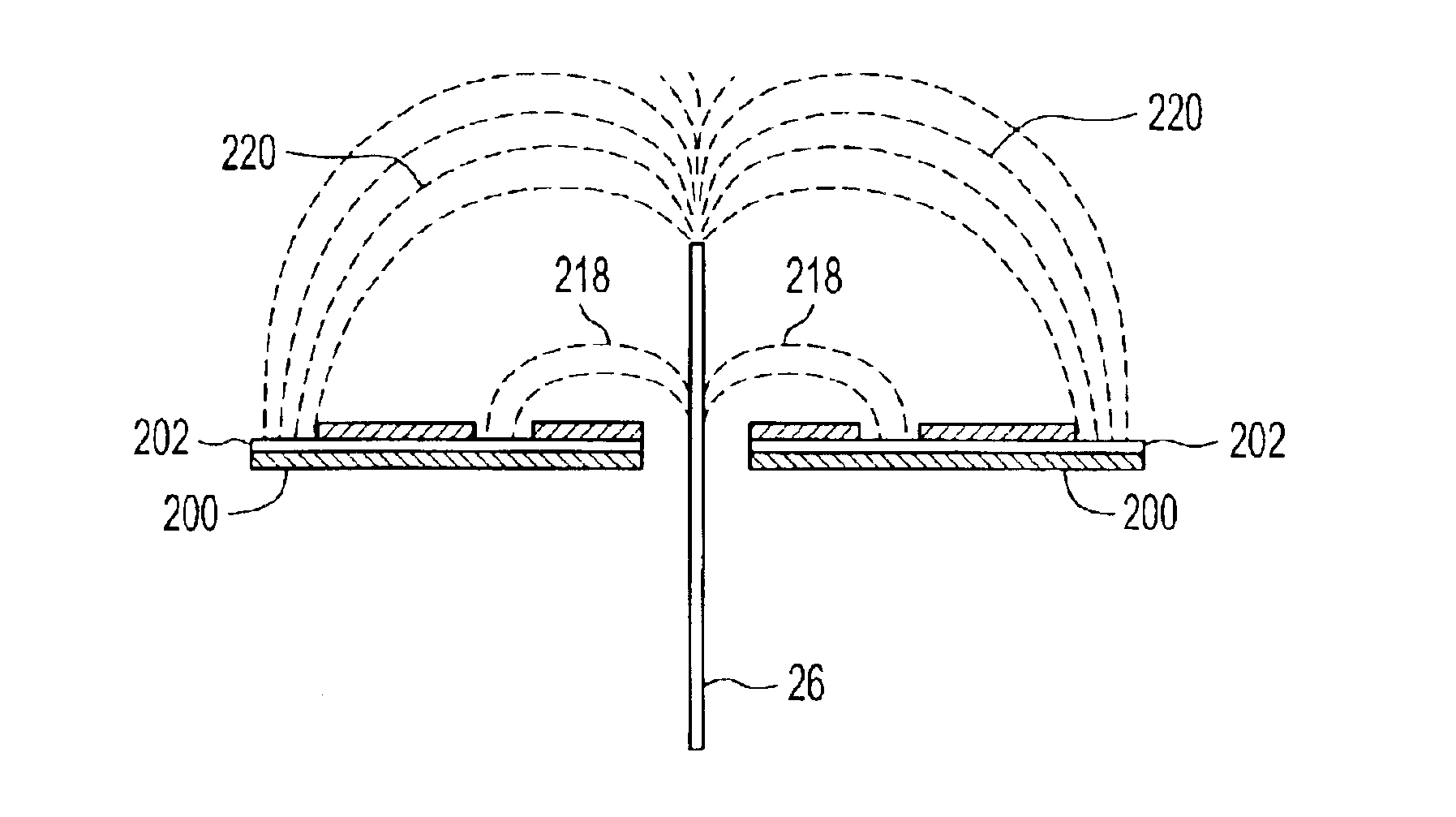
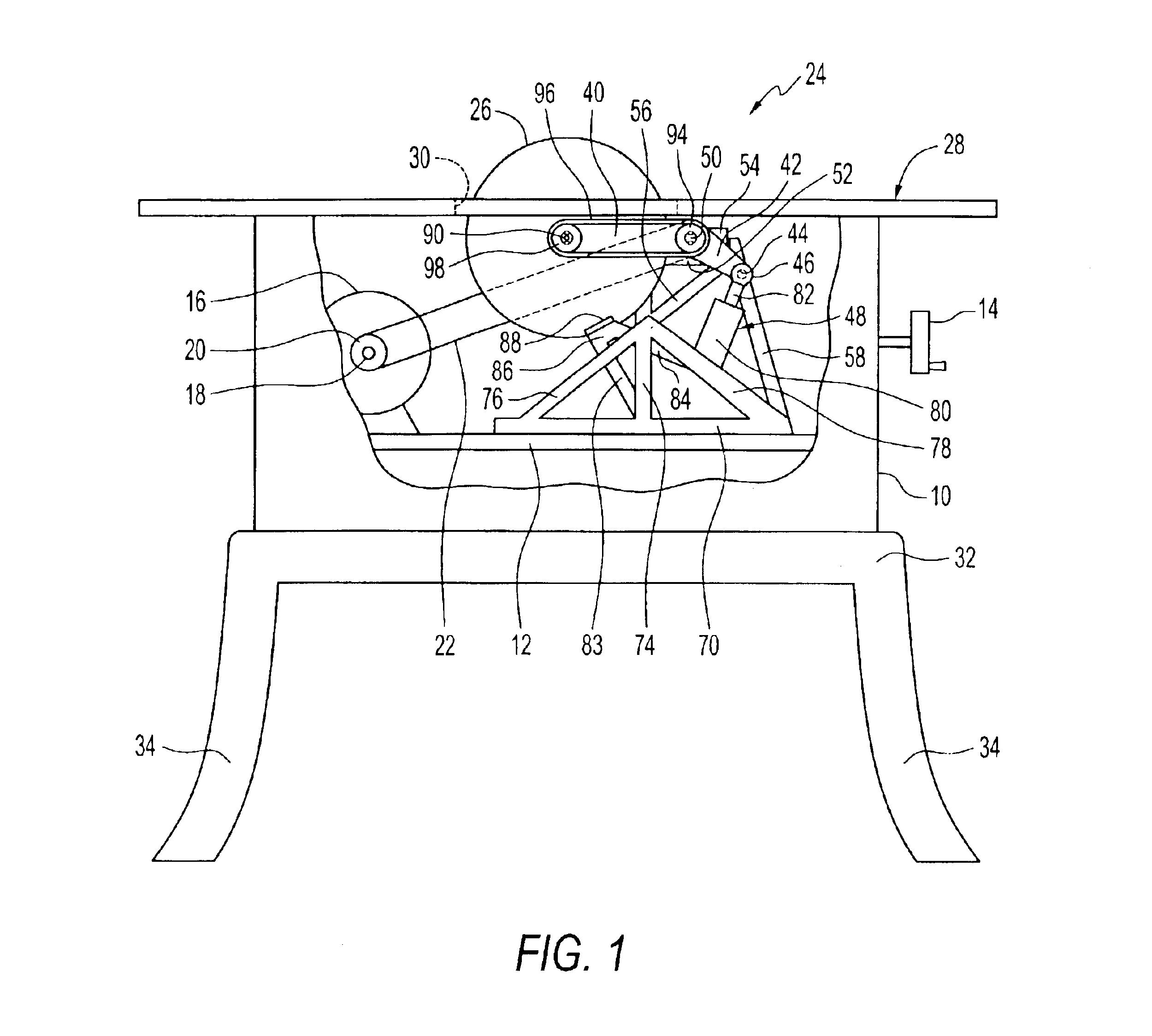
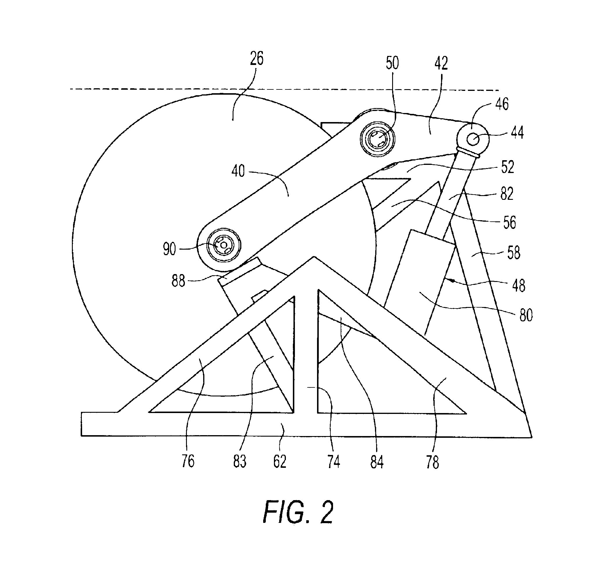
[0041]a protection system is shown in FIG. 1 together with a representative table saw design that includes a frame structure 10 that includes a platform 12 or other blade raising mechanism that is of conventional design to those of ordinary skill in the power tool art and is controlled by a hand wheel 14, a motor 16 having a drive shaft 18 and attached pulley 20 on which a belt 22 is coupled to a retraction mechanism, indicated generally at 24, and specifically drives a saw blade 26 that is a part of the retraction mechanism. A tabletop 28 has a top work surface with an elongated slotted opening 30 through which a portion of the blade 26 can extend. The tabletop 28 has important components of a detection system attached to it or embedded in it as will be described. The frame structure 10 may have a lower portion 32 including legs 34 as is conventional.

[0042]The embodiment of the retracting mechanism 24 shown in FIGS. 1-3, as well as the additional embodiments that are shown in FIGS....

second embodiment

[0050]With regard to a blade retracting mechanism and referring to FIGS. 4 and 5, a lever arm 122 is provided and pivots around shaft 124 and has a generally right angled extension 126 which has a curved outer end surface containing a rack gear portion 128. The left end of the lever arm 122 has an arbor 129 which carries the blade 26. As shown in FIGS. 4 and 5, the lever arm 122 is in its normal operating position with a significant portion extending above the work surface of the table saw which is diagrammatically illustrated by the dotted line in FIG. 4. The rack 128 is positioned to engage a worm gear 130 that is attached to a shaft 132 that has a hand wheel 134 attached to the left end portion thereof. By rotating the hand wheel 134, the worm gear 130 which is attached to the shaft 132 by means of an annular snap ring (not shown) that can be broken free to permit the worm gear 130 to be moved to the right relative to the shaft. The worm gear 130 engages the rack gear portion 128...

third embodiment

[0051]a blade retracting mechanism is shown in FIGS. 6-9, with the perspective view of FIG. 6 showing the mechanism in a normal operating position and FIGS. 7 and 8 showing it in a retracted position. In this embodiment, a lever arm 150 is provided which pivots around shaft 152 and it has a generally right angled extension 154 that has an actuator 156 attached thereto, with the actuator having a small cylindrical end portion 158 that engages an opening in the extension 154. This embodiment operates according to a different principle than the embodiments of FIGS. 1-5 in that the actuator 156 which has an extendable rod 160 operate together with a flywheel 162 that is driven by and is attached to a gear 164. The gear 164 and flywheel 162 are rotatably mounted on a shaft (not shown) that is attached to a bracket 166 having an arcuate slot 168 therein. The bracket 166 has a transverse cylindrically shaped extension 170 that fits within a bracket 172 that is attached to a frame structure...


PUM

PropertyMeasurementUnit
velocityaaaaaaaaaa
tensionaaaaaaaaaa
rotationaaaaaaaaaa

Abstract

A detection system for detecting a dangerous condition for an operator using a power tool of the type which has an exposed blade relative to a work surface and a protection system for minimizing, if not eliminating the possibility of a user being injured by contacting the blade. In one preferred embodiment of the present invention, a proximity detection system is capable of detecting the presence of a user near the blade of a table saw and a protection system that can either retract the blade below the work surface of the table saw or terminate the drive torque to the blade which can result in rapid stopping of the saw blade by a work piece that is being cut.

Description

BACKGROUND OF THE INVENTION[0001]The present invention generally relates to power tools, and more particularly, to safety detection and protection systems for power tools such as table saws of the type that are used for cutting wood and other materials.[0002]For as long as power tools have existed, there has been concern for the safety of those who operate them. This is particularly true with regard to power tools of the type which have relatively large exposed moving blades that can easily cause serious injury to individuals who carelessly use the tool or who are the victim of a true accident that results from unforeseen conditions. While safety systems have been developed for machine tools and other commercial tools, such as stamping tools, punch presses and other machines which exert great force in manufacturing metal and other parts, such systems often have a level of sophistication and complexity that is achieved only at a cost that is prohibitive if considered for use in tools...

Claims


Application Information

Patent Timeline
Patent Type & Authority Patents(United States)
IPC IPC(8): B23D45/06B23D59/00B23D47/00B23D47/08B23D45/00B27G19/00B27G19/02F16P3/14F16P3/00
CPCB23D45/067B23D47/08B23D59/001F16P3/148F16P3/14B23D45/06F16P3/12B27G19/02Y10T83/9384Y10T83/9372Y10T83/089Y10T83/081Y10T83/8773Y10T83/773
Inventor PIERGA, WOJCIECH T.SIWEK, THOMAS R.SHISHEGAR, AHMAD R.
Owner CREDO TECH CORP
Why Eureka
Try Eureka