
Bumper airbag and system

a bumper airbag and airbag technology, applied in bumpers, instruments, tractors, etc., can solve problems such as new problems in the collision area of vehicles, and achieve the effect of reducing the severity of collisions

Inactive Publication Date: 2005-08-02
FORD GLOBAL TECH LLC
View PDF22 Cites 71 Cited by
  • Summary
  • Abstract
  • Description
  • Claims
  • Application Information

AI Technical Summary

Benefits of technology

[0013]An advantage of the present invention is that it can reduce the severity of a collision between high standing vehicle and a low standing vehicle.
[0014]Another advantage of the present invention is that it offers protection to the occupant of the struck vehicle in the event the occupant is partially expelled in the direction of the invention.
[0015]These and other advantages will be found in the present invention that is directed to an airbag assembly mounted behind a vehicle's bumper coupled with sensors, electronic control units, and inflators to inflate by means of a fluid pressure to expand and provide an interface between a striking and struck motor vehicles. The airbag can have an up-side-down “L” shape or a cylindrical shape. Further, multiple bags can be combined within one system. The airbag is configured to cover substantially the width of the vehicle upon deployment and also provide protection to the occupant of a struck vehicle in the event the occupant is partially expelled from the struck vehicle in the direction of the bag.

Problems solved by technology

The increased popularity of sports utility vehicles, passenger trucks and other retail motor vehicles that stand higher than a standard motor vehicle, such as a sedan or sports car, has created new problems in the area of vehicle collisions.

Method used


Image

  • Bumper airbag and system
  • Bumper airbag and system
  • Bumper airbag and system

Examples


first embodiment

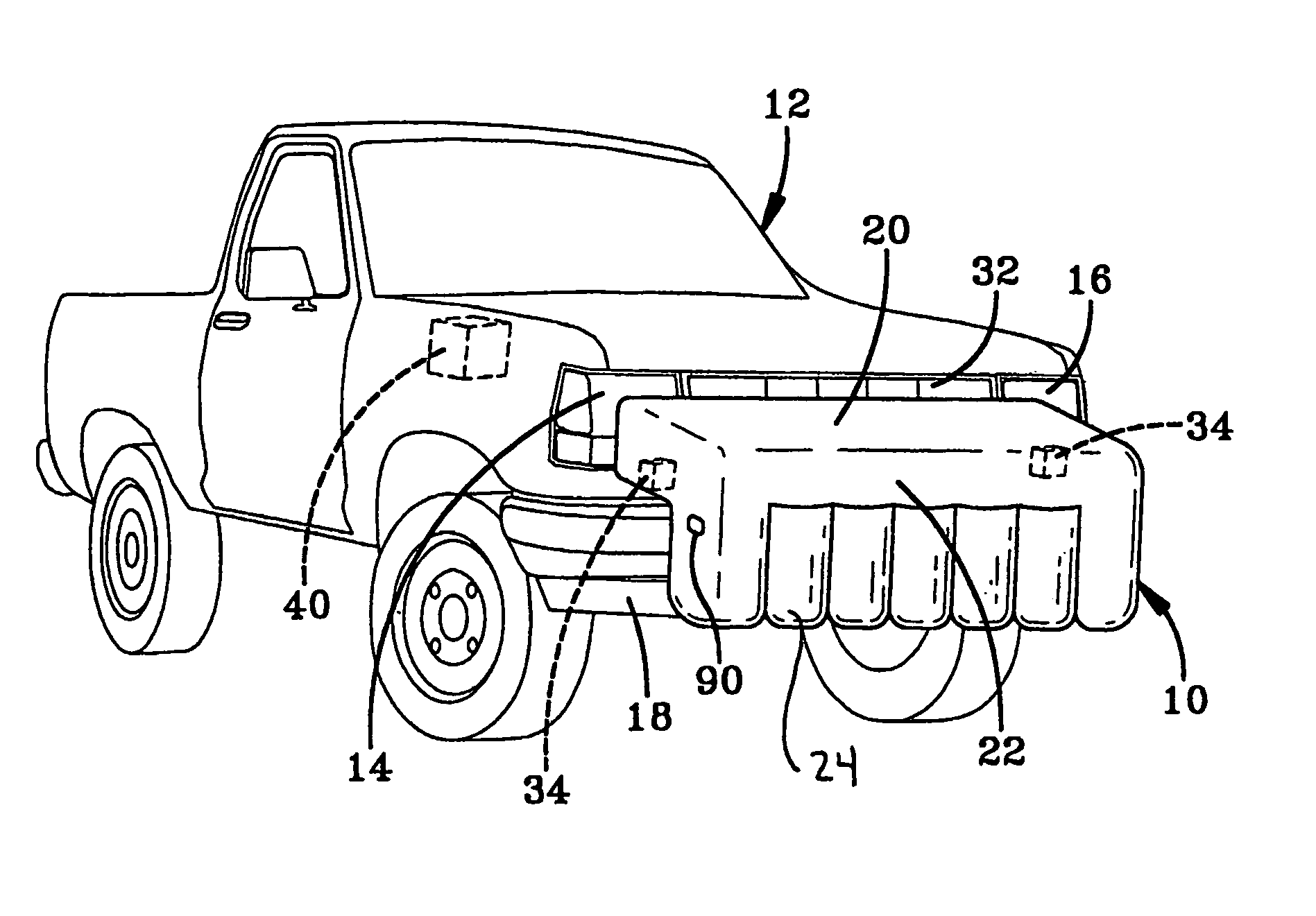
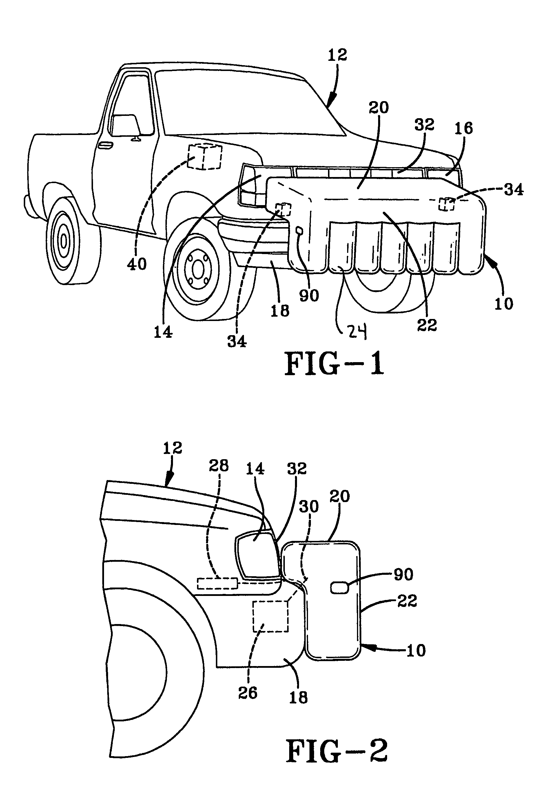
[0029]Referring to FIGS. 1–3, a bumper airbag as contemplated by the present invention is generally denoted by reference numeral 10. An important feature of the airbag 10 is its ability to extend across a substantial portion of the width of the vehicle. By substantial it is meant at least 65% of the width of the vehicle or extending at least between the vehicle's headlamps 14 and 16. It will be appreciated that the airbag can have a number of different shapes as will be described herein.

[0030]In the first embodiment of the present invention, the airbag 10 has a up-side-down “L” shape and extends forward from the bumper 18 along a base portion 20. An arm portion 22 extends perpendicularly downward from the base portion 20 and includes a plurality of tubular portions 24. In the preferred embodiment, the diameter of each of the tubular portions 24 is about nine inches (23 cm).

[0031]The airbag 10 is stored in a folded condition in a housing 26 mounted behind the bumper 18. At least one ...

second embodiment

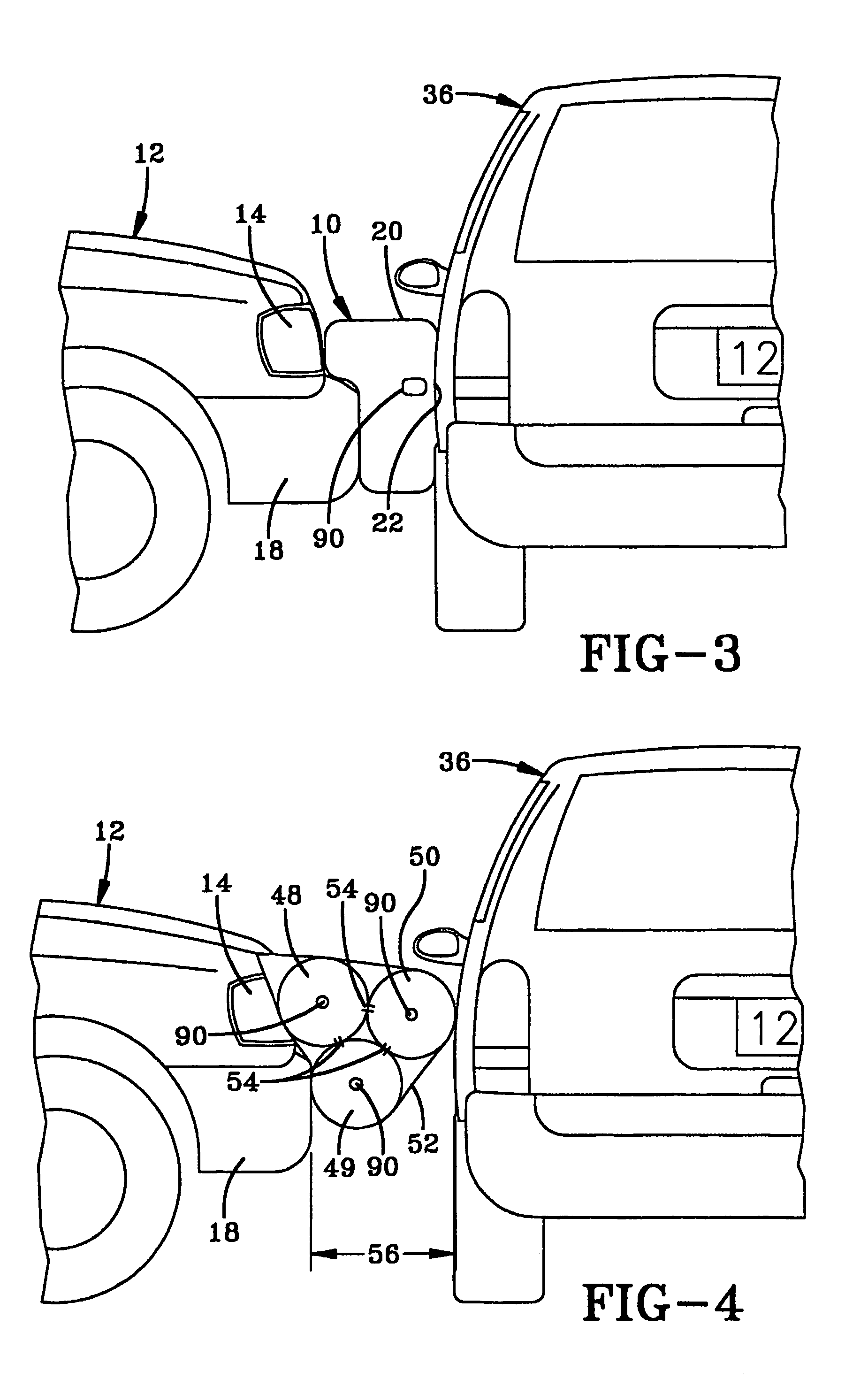
[0037]Referring to FIGS. 4–12, a bumper airbag as contemplated by the present invention is generally denoted by reference numeral 58. As with the airbag 10, an important feature of the airbag 58 is its ability, when inflated, to extend across a substantial portion of the width of the vehicle as shown in FIG. 11. The bumper airbag 58 when fully inflated is a circular cylindrical bag. Along the side 64 of the airbag 58 is a rectangular connecting housing or throat member 66, shown in FIG. 6, that couples the airbag 58 to a housing 96 disposed within the bumper 62 of vehicle 60. The throat member 66 is connected to the airbag 58 by a flange 65 surrounding the throat member. The flange 65 may be sewn or bonded to the airbag. The mating side of the flange 65 is shown in FIG. 6. Inside the throat 66 are preferably three inlets or holes 68, 69, 70, (see FIG. 8), in the wall of the airbag bag 58. As shown in FIG. 7 the connecting housing or throat 66 has parallel walls 74,76 with the wall 7...


PUM


Abstract

An airbag (10) for mounting in the bumper (18) of a motor vehicle (12) is provided. The airbag can have an up-side-down “L” shape or a cylindrical shape. Further, multiple bags can be combined within one system. The airbag is configured to cover substantially the width of the vehicle upon deployment and also provide protection to the occupant of a struck vehicle (36) in the event the occupant is partially expelled from the struck vehicle in the direction of the bag. The airbag is combined with an inflation (23), collision sensor (34) and an electronic control unit (38) to form the airbag system.

Description

CROSS REFERENCE TO RELATED APPLICATION[0001]This application claims priority to co-pending Provisional Patent Application having Ser. No. 60 / 261,056, filed Jan. 11, 2001, which is incorporated herein by reference.TECHNICAL FIELD[0002]This invention relates generally to motor vehicle safety devices and in particular to an inflatable airbag for use in the bumper area of a motor vehicle.BACKGROUND OF THE INVENTION[0003]For years, the automotive industry has tried various methods and products to reduce the damage to passengers and vehicles in collisions. Of prime importance are the various systems of vehicle airbags that are deployed upon the sensing of an actual collision. These airbags are located in and about the passenger compartment of the motor vehicle and are inflated to surround and protect the occupants from serious injury.[0004]Other methods of reducing, to some extent, the forces created in a collision from injuring the occupants are various attempts to provide “crush zones” ...

Claims


Application Information

Patent Timeline
Patent Type & Authority Patents(United States)
IPC IPC(8): B61F19/04B61F19/00B60R19/20B60R19/18B60R21/16B60R21/233B60R21/239B60R21/276B60R21/36
CPCB60R19/205B60R21/2338B61F19/04B60R21/239B60R21/276B60R2021/23107B60R2021/23386
Inventor CURRY, PAUL G.PACK, WESLEYHAILSTONE, STEVEBAKER, JEFFREY A.MCCLENATHAN, ROBERT V.VECCHIO, MICHAEL T.BARBAT, SAEED DAVIDPRASAD, PRIYARANJAN
Owner FORD GLOBAL TECH LLC
Learn More