Air compressor with extensible handle bar assembly

a technology of air compressor and handle bar, which is applied in the direction of positive displacement liquid engine, piston pump, liquid fuel engine, etc., can solve the problems of unwieldy storage and transportation, inability to easily access the pressure regulator and pressure gauge of the air compressor assembly to control the amount of pressure being provided to their tools, and large increase in the amount of air hose required to couple the air compressor assembly to each tool

Inactive Publication Date: 2005-08-02
BLACK & DECKER INC
View PDF15 Cites 49 Cited by
  • Summary
  • Abstract
  • Description
  • Claims
  • Application Information

AI Technical Summary

Benefits of technology

[0022]A fourth aspect of the present invention is directed to a novel apparatus for protecting the condensate removal device from damage caused by contact with foreign objects. The fourth aspect of the present invention is directed towards a shield that prevents objects from coming into contact with the condensate removal device. The fourth aspect of the present invention is further directed to a recessed condensate removal device where the condensate removal device may be recessed within a mounting device that to prevent damage to the condensate removal device by shielding contact from foreign objects. Furthermore, the fourth aspect of the present invention is directed to a removable cap that may be placed around and cover the condensate removal device.

Problems solved by technology

As a result, the amount of air hose required to couple the air compressor assembly to each tool is greatly increased, in many cases becoming unwieldy to store and transport.
Furthermore, because workers are remotely located from the air compressor assembly, they often cannot readily access the air compressor assembly's pressure regulator and pressure gauges to control the amount of pressure being provided to their tools.
However, a typical transport handle assembly is not suited for lifting the air compressor assembly, such as when the air compressor assembly is loaded into a truck, needs to be transported over stairs, is lifted over uneven ground, and the like.
Furthermore, an air compressor assembly may weigh hundreds of pounds, thereby requiring a substantial force to be exerted to lift the air compressor assembly.
The failure of the typical transport handle assembly to supply an accommodating way of lifting the air compressor assembly often requires users, when trying to lift the air compressor assembly to wrap their arms around the air storage tank, grasp a wheel assembly, grip the motor assembly, and engage in other very difficult and unsure maneuvers.
These maneuvers may cause damage to the air compressor assembly and even injury to the user due to the size and weight of a typical air compressor assembly.
Since compressed air tanks tend to be large and heavy, they may not be easily transported.
However, in many construction sites, movement to a remote location over an uneven and unpaved surface may be necessary.
A frequent problem that occurs while moving the compressed air tank to a remote location is that the drain valve for removing condensate from an air tank may be damaged during transport to a remote location.
Foreign objects tend to come into contact with the valve during transport causing damage to the valve.
Another problem is that compressed air tanks may be moved during the day and typically are placed upon the bed of a pickup truck in order to transport the compressed air tank to another worksite.
Since typical compressed air tanks are heavy, it is not easy for persons to use care and caution when placing the compressed air tanks onto the bed of a pickup truck.
Often, other items located on the bed of the truck may come into contact with the drain valve damaging the valve when the compressed air tank is placed upon the bed of a pickup truck.
Upon damage to the drain valve, the compressed air tank becomes non-functional.
One long unresolved problem with such air compressor assemblies is that they tend to be top heavy due in part to the weight of the compressor above the compressed air storage tank.
However, when such air compressor assembly 5-100 is utilized in more austere environments, such as at a construction site, where the air compressor assembly 5-100 is much more likely to rest on rough or uneven ground, it has been discovered that excessive tension (such as a sharp pull or jerk) applied to an air hose coupled to the air compressor in a direction generally perpendicular to the side of the compressed air storage tank 5-104 can cause the air compressor assembly 5-100 tip over as shown by arrow 5-108, possibly damaging the air compressor assembly or injuring its user.
Similarly, when such air compressor assembly is loaded into a vehicle such as a pickup truck, or the like for transport, movement of the vehicle may cause the air compressor assembly 5-100 to tip over possibly damaging the air compressor assembly 5-100 and the vehicle.
As a result, many users consider air compressor assemblies having such horizontal compressed air storage tanks less desirable for use in harsh environments than air compressor assemblies having other tank configurations.

Method used


Image

  • Air compressor with extensible handle bar assembly
  • Air compressor with extensible handle bar assembly
  • Air compressor with extensible handle bar assembly

Examples


Embodiment Construction

[0091]Reference will now be made in detail to the presently preferred embodiments of the invention, examples of which are illustrated in the accompanying drawings.

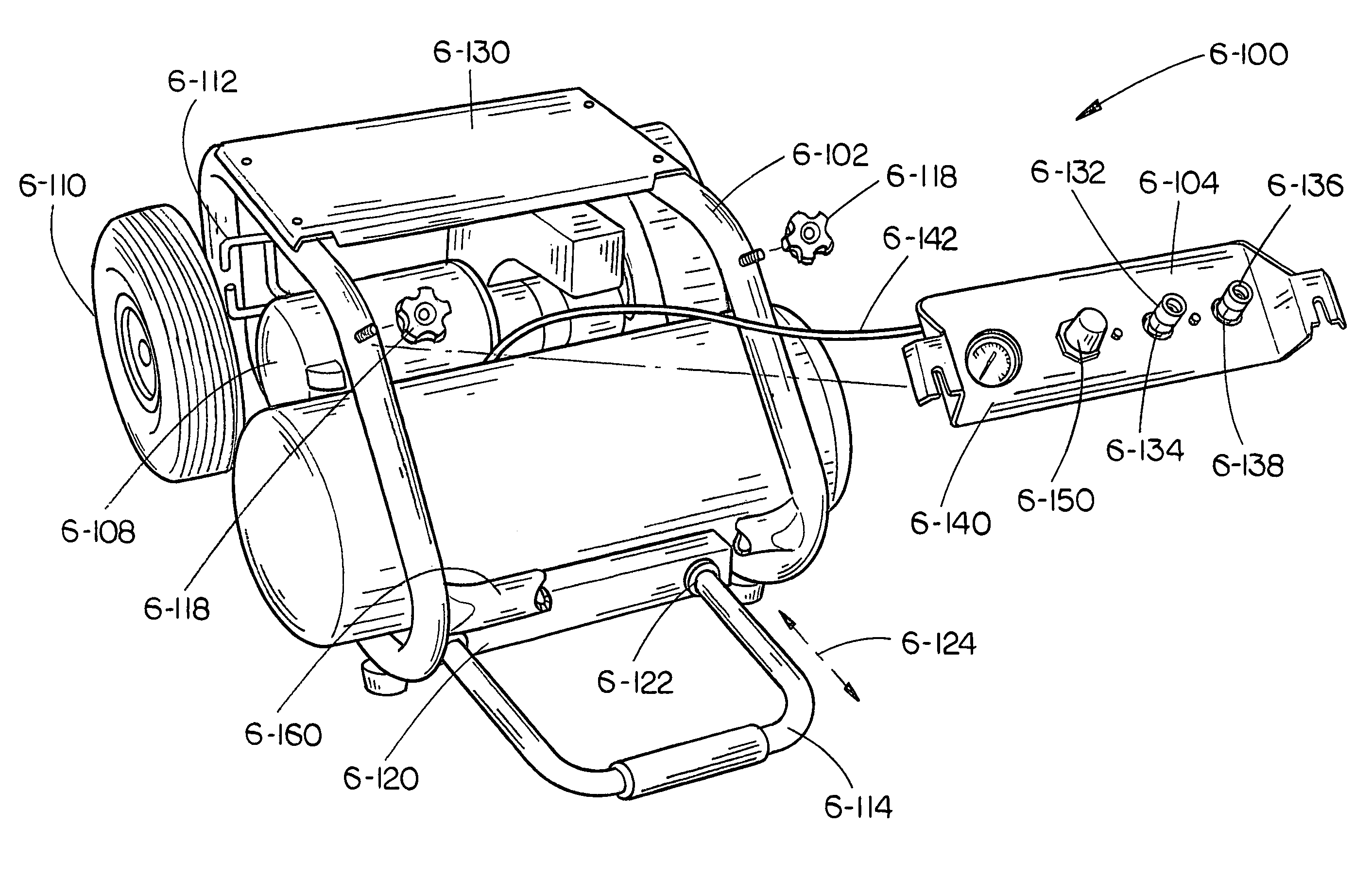
[0092]Referring generally to FIGS. 2 through 14, exemplary embodiments of a first aspect of the present invention directed to a manifold assembly for an air compressor assembly that is capable of controlling and distributing compressed air from the air compressor assembly to one or more air powered tools are shown.

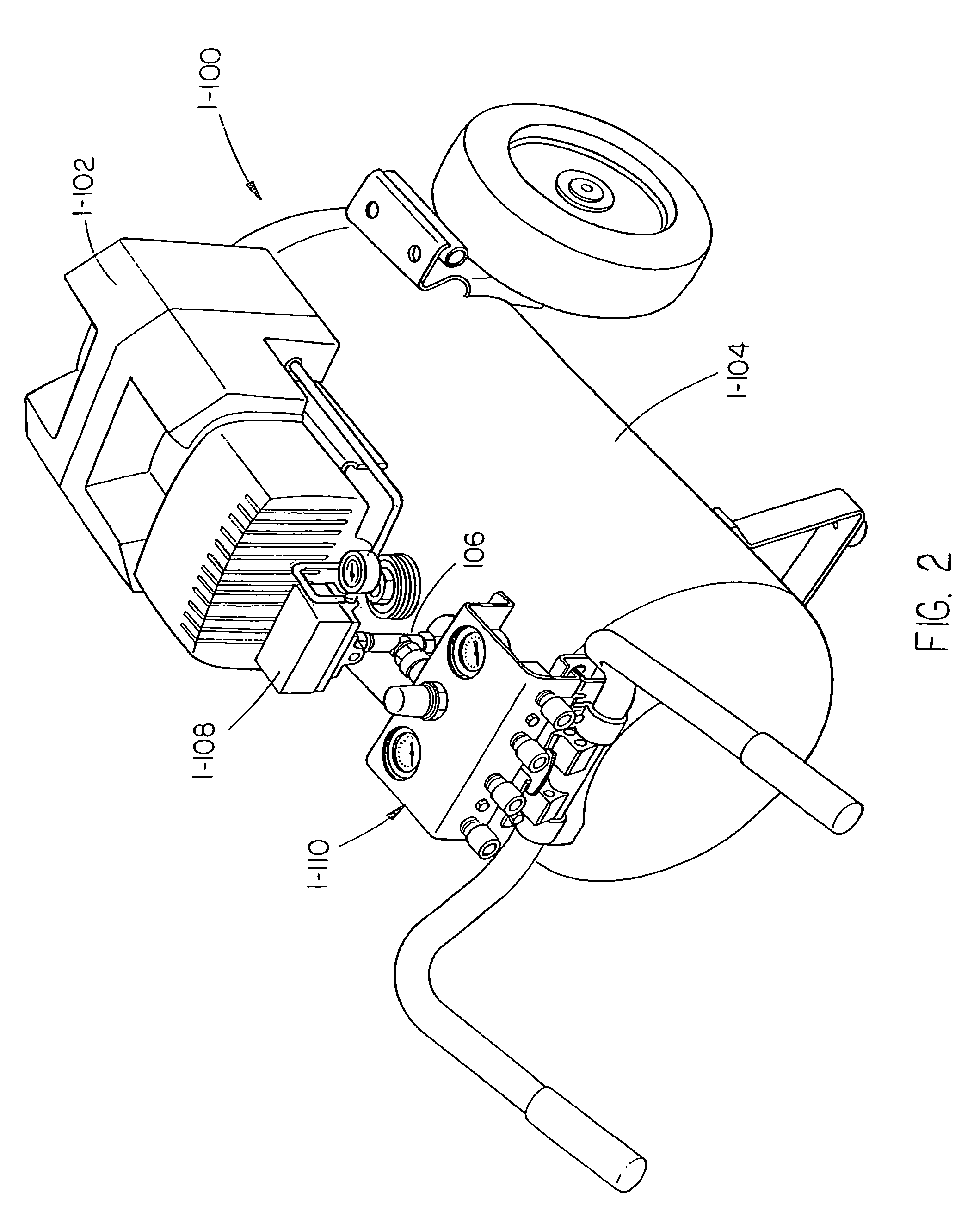
[0093]Referring generally to FIGS. 2 through 5, an air compressor assembly 1-100 in accordance with an exemplary embodiment of the present invention is described. As shown in FIGS. 2 and 3, the air compressor assembly 1-100 includes a compressor 1-102 mounted to a compressed air storage tank 1-104. The compressed air storage tank 1-104 provides a tank or receiver for storing air under pressure. A port (often referred to as a “spud”) is provided in the compressed air storage tank 1-104 to which a pressure manifold...


PUM


Abstract

An air compressor assembly with one or more of the following features: a removable manifold assembly capable of being remotely located from the air compressor assembly for controlling and distributing compressed air from the air compressor assembly to one or more air powered tools, a lifting handle, a handle capable of assuming a plurality of positions, condensate removal devices, and a stable base and tie-down points.

Description

CROSS-REFERENCE TO RELATED DOCUMENTS[0001]The present application is a continuation-in-part of U.S. application Ser. No. 10 / 277,187, filed Oct. 21, 2002, now U.S. Pat. No. 6,742,995. Said U.S. application Ser. No. 10 / 277,187 itself is a continuation-in-part of U.S. application Ser. No. 09 / 802,149, filed Mar. 8, 2001, U.S. Pat. No. 6,655,925, which claims the benefit under 35 U.S.C. § 119(e) of U.S. Provisional Application Ser. No. 60 / 187,744, filed Mar. 8, 2000; said U.S. application Ser. No. 10 / 277,187 is a continuation-in-part of U.S. application Ser. No. 09 / 801,406, filed Mar. 8, 2001, U.S. Pat. No. 6,532,990, which claims the benefit under 35 U.S.C. § 119(e) of U.S. Provisional Application Ser. No. 60 / 187,680, filed Mar. 8, 2000; said U.S. application Ser. No. 10 / 277,187 is a continuation-in-part of U.S. application Ser. No. 09 / 801,408, filed Mar. 8, 2001, U.S. Pat. No. 6,532,991, which claims the benefit under 35 U.S.C. § 119(e) of U.S. Provisional Application Ser. No. 60 / 187,7...

Claims


Application Information

Patent Timeline
Patent Type & Authority Patents(United States)
IPC IPC(8): F04B35/00F04B35/06F04B41/02F04B41/00F04B49/00B67D99/00
CPCF04B35/06F04B41/02F04B49/00Y10T137/8326
Inventor WOOD, MARK W.BURKHOLDER, ROBERT F.BARBOUR, CRANDALL B.DAVIS, MIKE L.MORGAN, FRED M.ROBENALT, DAVID W.SMITH, DAVE C.HARDIN, JOHN W.STILWELL, J. CODYWHITE, GARYVOS, STEPHEN J.
Owner BLACK & DECKER INC
Why Eureka
Try Eureka