Filter cartridge having bypass feature

a filter cartridge and bypass technology, applied in the field of filtration systems, can solve the problems of increasing costs, and high removal rate, and reducing the life of the filter

Inactive Publication Date: 2005-08-02
CUNO +1
View PDF3 Cites 18 Cited by
  • Summary
  • Abstract
  • Description
  • Claims
  • Application Information

AI Technical Summary

Benefits of technology

[0022]A proximal radial seal disposed along the outer periphery of the elongated portion of the neck, adjacent the proximal end portion, provides a substantially water-tight engagement between the neck and the receiving core. A distal radial seal disposed along the outer periphery of the elongated portion of the neck, adjacent the distal end portion, provides an

Problems solved by technology

Customization of the filter cartridges to meet the desired filtration ability will result in increase costs.
However, a high level of calcium and magnesium removal is not desirable for all applications, such as applications requiring “recipe quality water” (e.g., beverage mixing applications) that must maintain a level of hardness within a constant range to deliver an end product having a pleasing taste, among other things.
In addition, a high rate of removal reduces the life of the filter, and thus, filtration capability.
It is unnecessary for these end users to pay h

Method used


Image

  • Filter cartridge having bypass feature
  • Filter cartridge having bypass feature
  • Filter cartridge having bypass feature

Examples


Embodiment Construction

[0039]The advantages of a filtration assembly constructed or retrofitted in accordance with the present invention will become more readily apparent to those having ordinary skill in the art from the following detailed description of certain preferred embodiments taken in conjunction with the drawings which set forth representative embodiments thereof. Unless otherwise apparent, or stated, directional references, such as “lower” and “upper”, are intended to be relative to the orientation of a particular embodiment of the invention as shown in the first numbered view of that embodiment. Also, a given reference numeral indicates the same or similar structure when it appears in different figures.

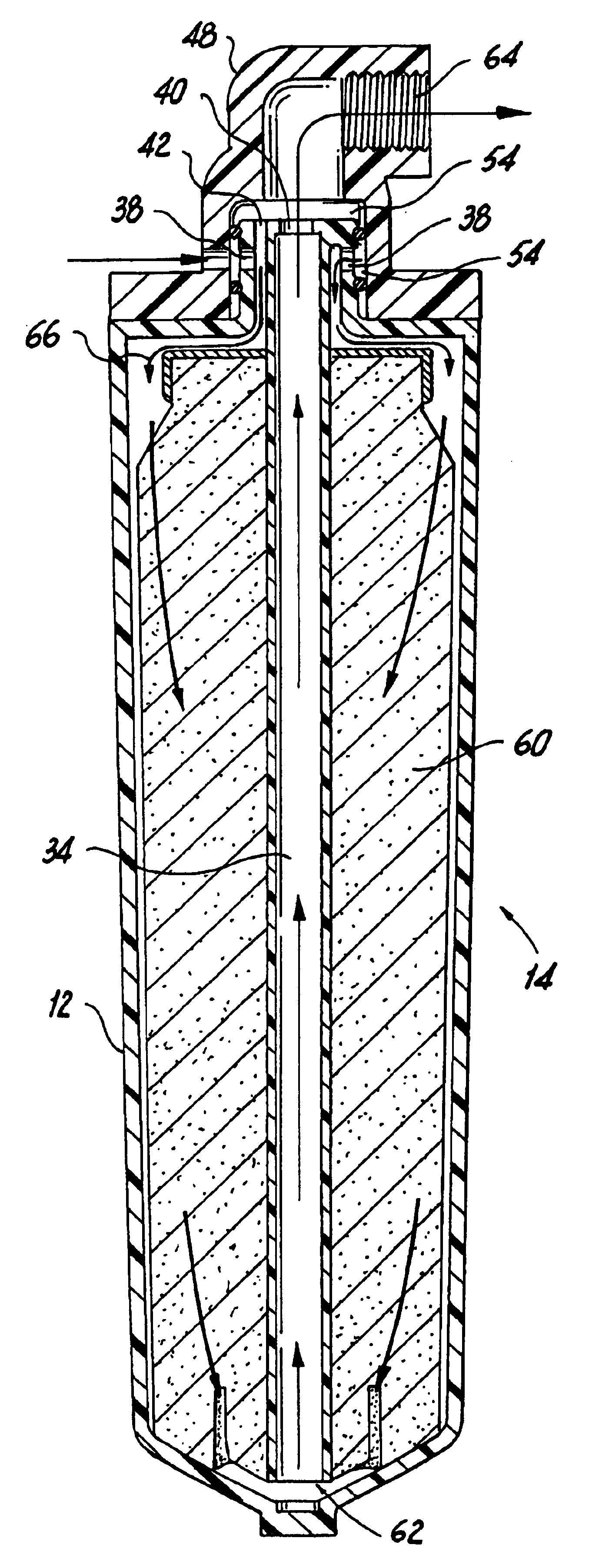
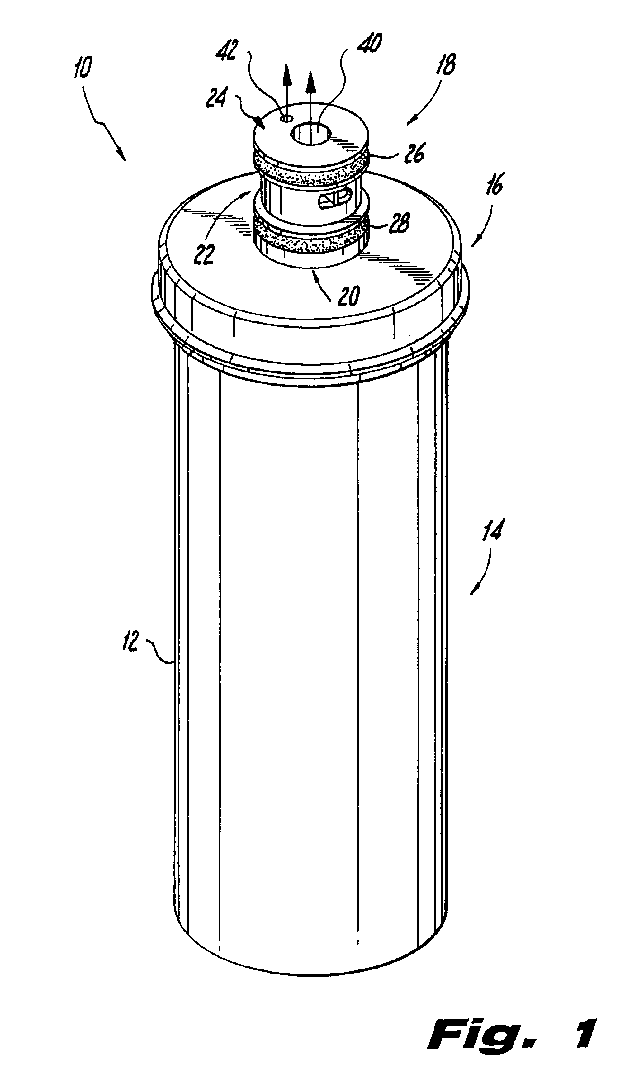
[0040]Referring now to FIG. 1, in which there is illustrated a filter cartridge constructed in accordance with a preferred embodiment of the present disclosure and designated by reference numeral 10. Filter cartridge 10 includes a main housing 12, preferably cylindrically-shaped, which includes ...


PUM

PropertyMeasurementUnit
Diameteraaaaaaaaaa
Diameteraaaaaaaaaa
Diameteraaaaaaaaaa

Abstract

A filter cartridge 10 includes a connective end for mating with a filter head 48 and providing fluid communication between the filter media chamber and the filter head. The connective end includes a tubular member 34 disposed axially in a hollow neck 18 to define inner and radially outer axial passages (30, 32) providing independent conduits for dual flow through the neck. The outer axial passage includes an opening 38 in the elongated portion 22 of the neck and a bypass opening 42 in the distal end portion of the neck. The inner axial passage includes an opening 40 in the distal end of the neck. Proximal and distal radial seals (26, 28) are provided on the outer periphery of the elongated neck portion 22 to ensure water-tight engagement when the neck is inserted into the receiving core of the filter head.

Description

BACKGROUND OF THE INVENTION[0001]1. Field of the Invention[0002]The present application relates to filtration systems which include replaceable filter cartridge housings that have a bypass feature associated therewith, more particularly, to filter cartridge housings which include a bypass channel that allows fluid to proceed from the inlet portion of the cartridge to the discharge portion of the cartridge without contacting the filer media disposed within the cartridge housing, and still more particularly, to a replaceable cartridge which provides economic advantages through improved filtration capacity while maintaining the hardness of the water output within a desirable range.[0003]2. Background of the Related Art[0004]Often in both consumer and industrial applications a fluid, such as water, is filtered prior to its use in an intended application. As a result, filtration systems are installed either internally or externally within the industrial system or consumer appliance. For ...

Claims


Application Information

Patent Timeline
IPC IPC(8): B01D35/14B01D35/157C02F9/00C02F1/28
CPCB01D35/157C02F9/005B01D35/30B01D2201/302C02F1/283C02F2201/006C02F9/20
Inventor MCGIBBON, DONALD
Owner CUNO
Why Eureka
Try Eureka