System and method for monitoring current and providing motor protection

a technology of current monitoring and motor protection, applied in the field of motor controllers, can solve problems such as imbalance of delta motors, damage to a single winding, and imbalance determination

Inactive Publication Date: 2005-08-02
SIEMENS ENERGY & AUTOMATION INC
View PDF6 Cites 14 Cited by
  • Summary
  • Abstract
  • Description
  • Claims
  • Application Information

AI Technical Summary

Benefits of technology

[0011]In accordance with the invention there is provided a system and method for monitoring current and providing motor protection.

Problems solved by technology

The controller switches are wired inside the delta. Delta motors may be imbalanced.
However, this could result in damage to a single winding if, for example, the single winding has an excessive current and the remaining winding currents are within limits so that the average current is less than the overload setting.
However, imbalance is determined by comparing measured currents to a fixed trip level.

Method used


Image

  • System and method for monitoring current and providing motor protection
  • System and method for monitoring current and providing motor protection
  • System and method for monitoring current and providing motor protection

Examples


Embodiment Construction

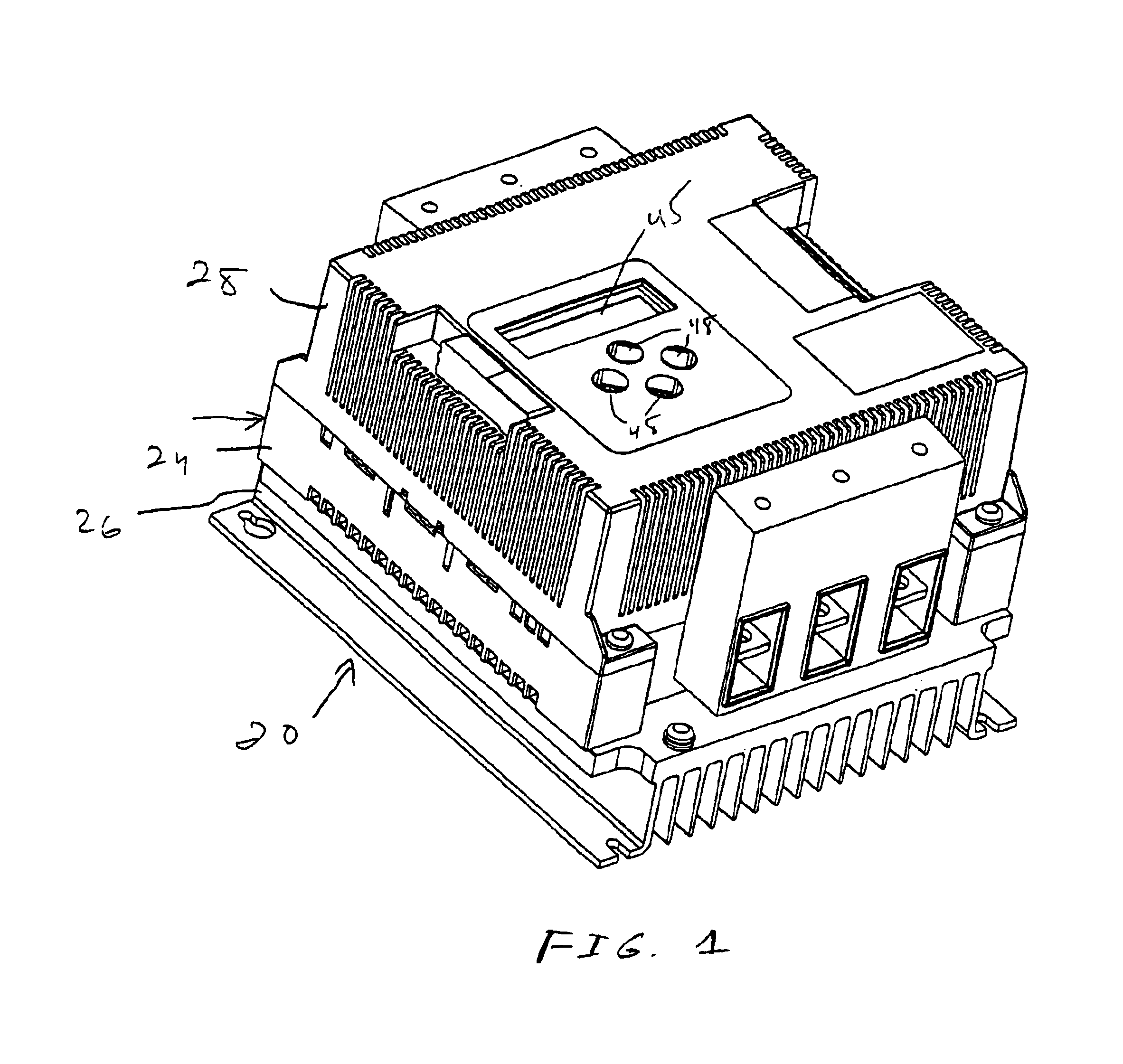
[0027]Referring initially to FIG. 1, a solid state motor starter / controller 20, referred to hereinafter as simply a starter or a controller, is illustrated. One application for the controller 20 is as an elevator starter. The motor controller 20 may be used to drive a pump for an hydraulic elevator. Each time movement of an elevator car is commanded, then the motor controller 20 must start the elevator motor until it reaches operating speed and then operate in a run mode. Such a motor controller 20 may only be used for the up direction as gravity may be used for the down direction.

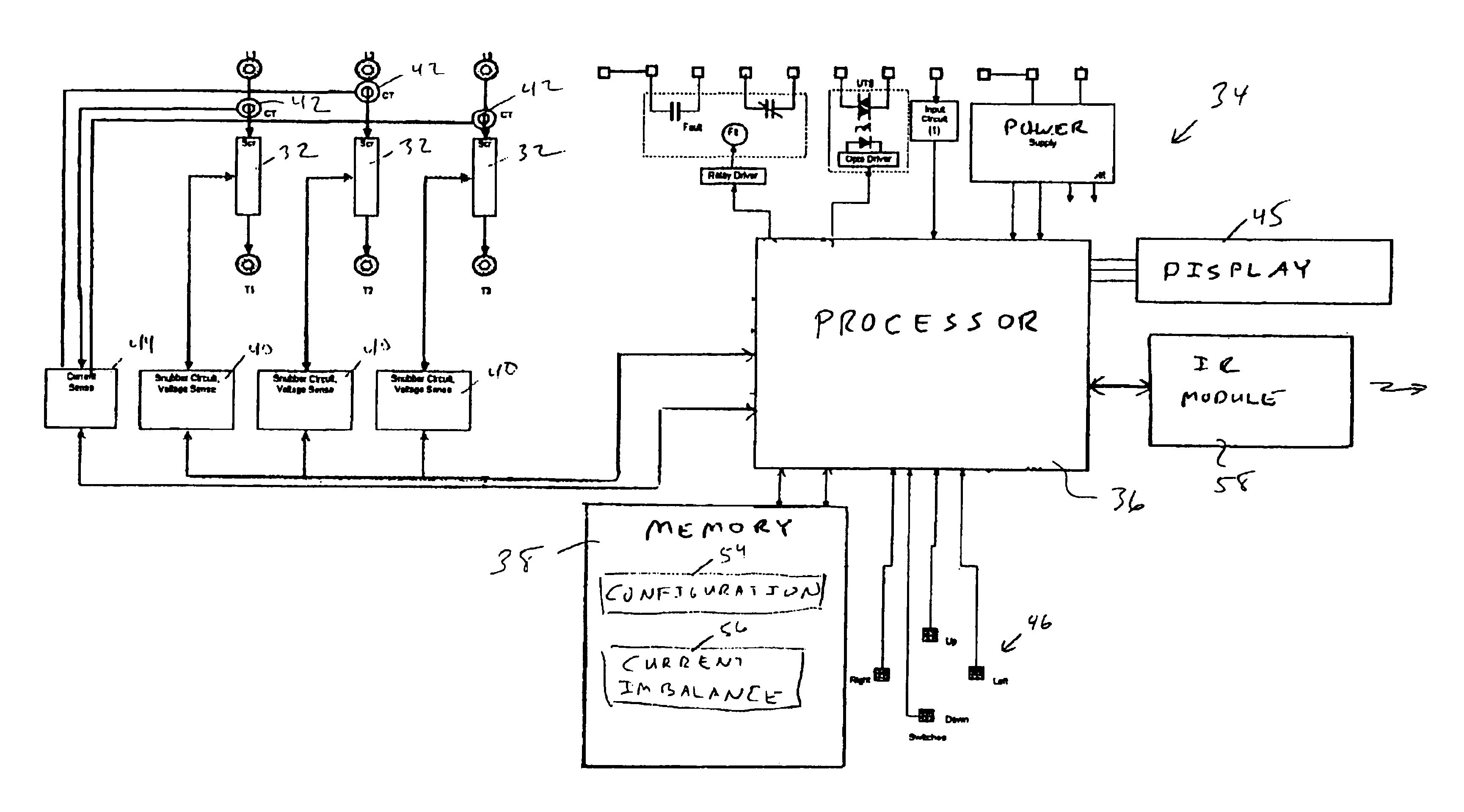
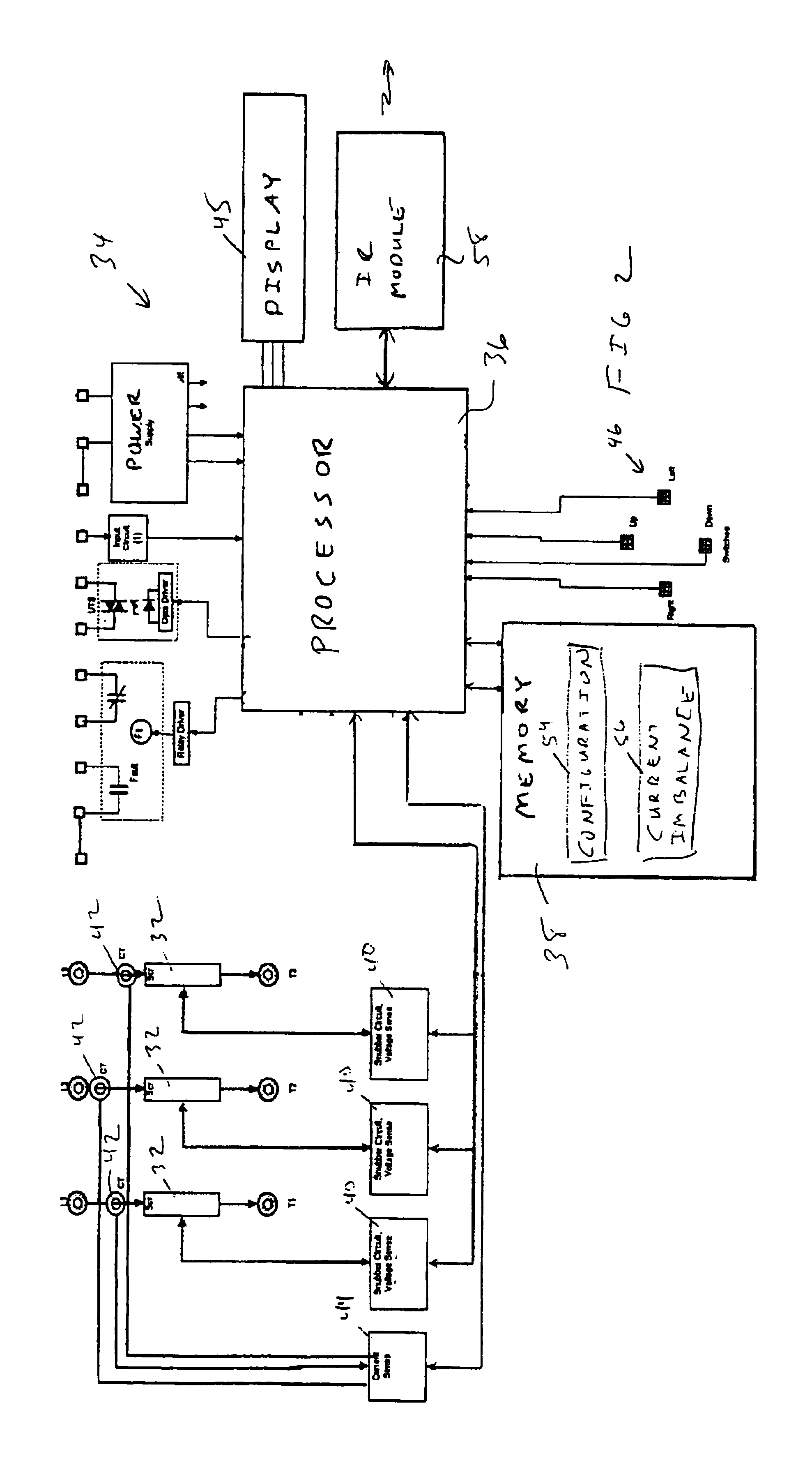
[0028]The motor controller 20 comprises a housing 22 including a housing base 24, a heat sink 26 and a cover 28. The motor controller 20 includes a plurality of solid state switches 32 in the form of thyristors, such as back to back connected silicon controlled rectifier (SCR) pairs, see FIG. 2. For simplicity herein, the SCR pairs 32 are referred to as simply SCRs. Triacs could also be used. The SCRs 32 c...


PUM


Abstract

A motor controller system comprises solid state switches for connection between an AC line and motor terminals for controlling application of AC power to the motor. A user input elements selects a current imbalance parameter. Current sensors sense current in each winding of the motor. A control circuit controls operation of the solid state switches. The control circuit compares the sensed currents with the selected imbalance parameter to determine if a fault condition exists.

Description

CROSS REFERENCE TO RELATED PATENT APPLICATIONS[0001]The present U.S. patent application having at least one common inventor as[0002]U.S. patent application Ser. No. 10 / 252,326 entitled “System and Method for Configuring a Starter with an External Device”, and[0003]U.S. patent application Ser. No. 10 / 252,635 entitled “System and Method for Individual Phase Motor Over Voltage Protection”, and[0004]U.S. patent application Ser. No. 10 / 252,637 entitled “System and Method for Automatic Current Limit Control”, and[0005]U.S. patent application Ser. No. 10 / 252,327 entitled “System and Method for a Configurable Motor Controller”,are filed with the U.S. Patent and Trademark Office concurrently on Sep. 23, 2002, the entirety of each being incorporated herein by reference.FIELD OF THE INVENTION[0006]This invention relates to a motor controller and more particularly, a system and method for monitoring current and providing motor protection.BACKGROUND OF THE INVENTION[0007]Solid state starters / con...

Claims


Application Information

Patent Timeline
Patent Type & Authority Patents(United States)
IPC IPC(8): H02K17/02H02K17/32H02P7/00H02P29/02
CPCH02P29/02
Inventor JONSSON, GREGGMAYHEW, SCOTTWAKEFIELD, SCOTTZUZULY, DANIEL
Owner SIEMENS ENERGY & AUTOMATION INC
Why Eureka
Try Eureka