Method for identifying risks as a result of stray currents

a technology of stray currents and risks, applied in the field of identifying risks as a result of stray currents, can solve the problems of stray currents flowing to the ground and to the structures at risk, corrosion of these structures, and electrical damage to the insulation between the rails and ground in one direction, so as to achieve easy evaluation

Inactive Publication Date: 2005-08-02
SIEMENS AG
View PDF6 Cites 10 Cited by
  • Summary
  • Abstract
  • Description
  • Claims
  • Application Information

AI Technical Summary

Benefits of technology

[0009]An embodiment of the invention is based on an object of specifying a simple and reliable method for identifying stray current risks whi...

Problems solved by technology

The flow of current can result in corrosion of these structures, for example, if they are made of metal.
The insulation between the rails and ground can become damaged or electrically bridged in another way over the course of time, how...

Method used


Image

  • Method for identifying risks as a result of stray currents
  • Method for identifying risks as a result of stray currents

Examples


first embodiment

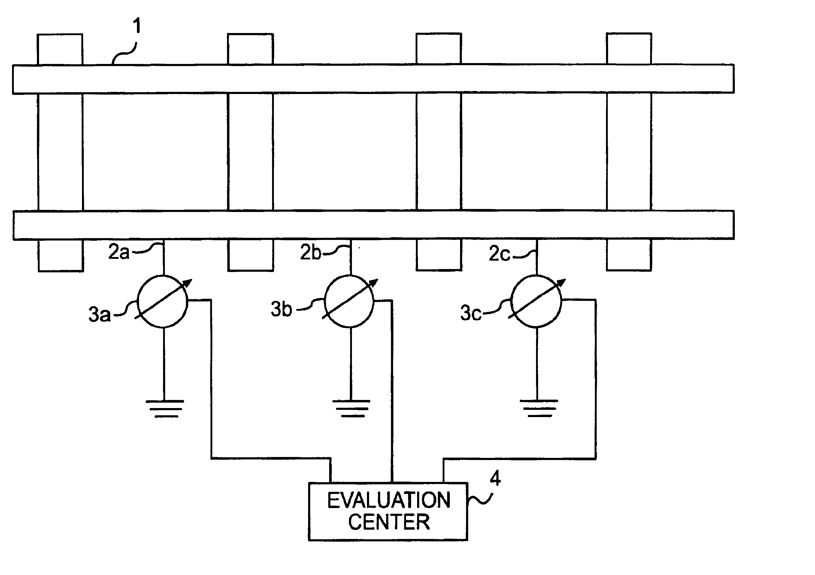
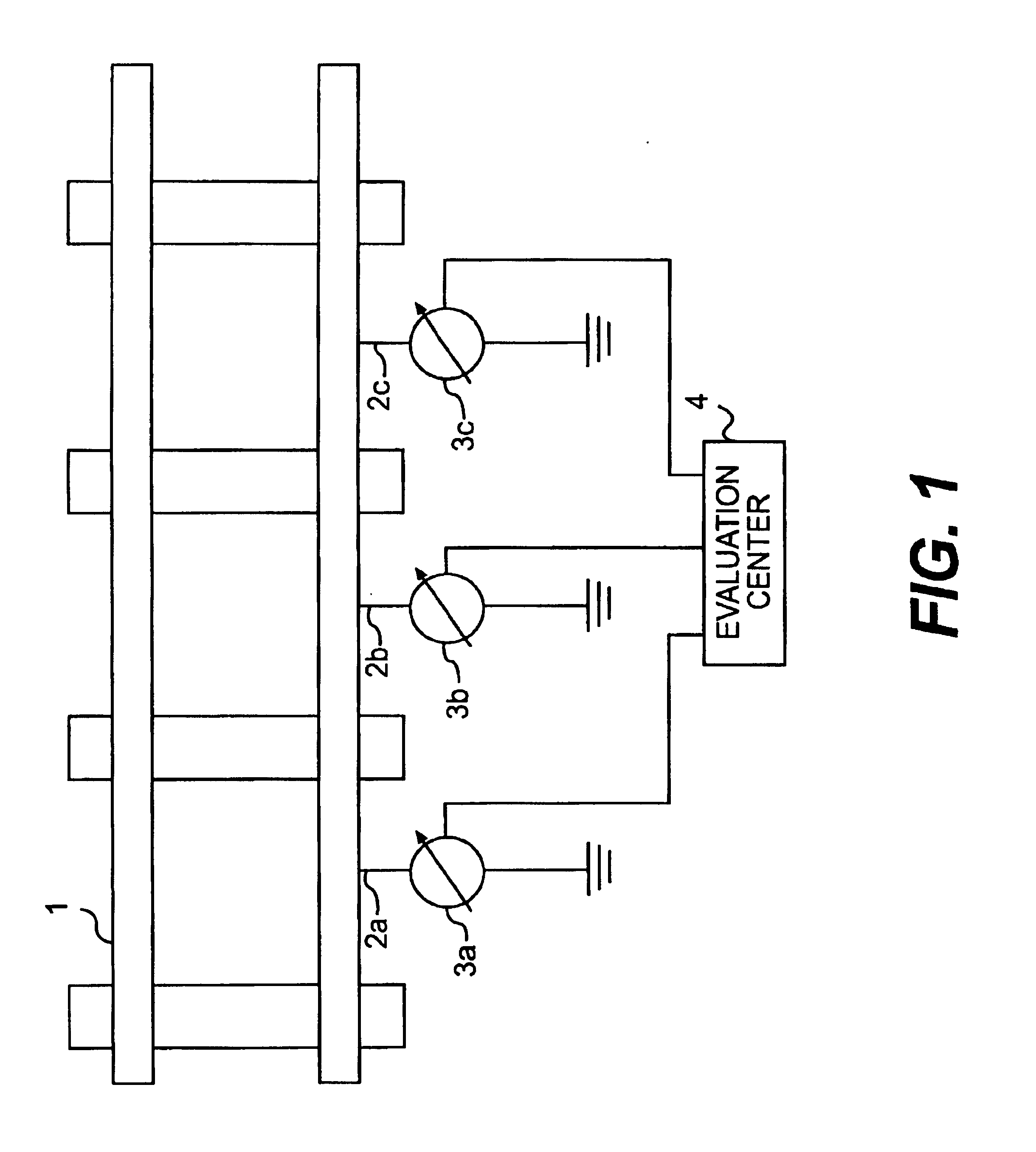
[0011]In accordance with a first embodiment, in which the voltage between the rail 1 and the ground is measured and an increased risk as a result of stray currents is indicated if there is a discrepancy from a voltage reference value, an object may be achieved by virtue of the voltage being measured at a plurality of measurement points 2a, 2b, 2c along the track and by virtue of the measurements being transmitted to an evaluation center 4 where they are evaluated centrally.

[0012]An advantage attained is that a plurality of simple voltage measurements suffice in order to obtain a reliable statement about the risk. These voltage measurements can be ascertained at a plurality of measurement points 2a, 2b, 2c using simple voltage measuring instruments 3a, 3b, 3c and are easy to evaluate in an evaluation unit 4. This involves a comparison with reference values.

second embodiment

[0013]In accordance with a second embodiment, an object may be achieved by virtue of activating a short-circuiter connecting a parallel path to the rail 1 for returning the traction current, by virtue of the current level in the parallel path being measured, and by virtue of an increased risk as a result of stray currents being indicated if there is a discrepancy from a current-level reference value.

[0014]Such a parallel path is a continuous tunnel reinforcement, for example. The parallel path is connected when required using a short-circuiter.

[0015]The second embodiment of the method in accordance with the invention involves the insight that current-level measurement in the parallel path can indicate damage to the insulation between the rail 1 and ground. This is because damage to this insulation reduces the electrical resistance of the rail 1 with respect to ground. Thus, a larger current is drained at that point. Since the electrical resistance of the parallel path remains the sa...


PUM


Abstract

A method is for identifying risks as a result of stray currents which flow to ground from a rail which returns a traction current in a track with a DC power supply. In accordance with a first embodiment, in which the voltage between the rail and ground is measured and an increased risk as a result of stray currents is indicated if there is a discrepancy from a voltage reference value, provision is made for the voltage to be measured at a plurality of measurement points along the track and for the measurements to be evaluated in an evaluation center. In accordance with a second embodiment, provision is made for activating a short-circuiter to connect a parallel path to the rail for returning the traction current. The current level in the parallel path is then measured and an increased risk as a result of stray currents is indicated if there is a discrepancy from a current-level reference value. Further, the method includes joint evaluation of a plurality of measurements which have been ascertained along the track.

Description

[0001]The present application hereby claims priority under 35 U.S.C. §119 on German patent application number DE 10236943.7 filed Aug. 12, 2002, the entire contents of which are hereby incorporated herein by reference.FIELD OF THE INVENTION[0002]The invention generally relates to a method for identifying risks as a result of stray currents.BACKGROUND OF THE INVENTION[0003]Stray currents flow to the ground (into the soil of the earth) from a rail which returns traction current in a track with a DC power supply.[0004]Normally, the rails in DC railways are used to return current. The rails are therefore insulated from the ground. This is because no current is intended to flow from the rails through the ground into surrounding conducting structures. Such structures can be parts of building foundations or tunnel systems, or else pipeline systems. The flow of current can result in corrosion of these structures, for example, if they are made of metal.[0005]The insulation between the rails ...

Claims


Application Information

Patent Timeline
IPC IPC(8): G01R31/02
CPCG01R31/025G01R31/52B60M5/00
Inventor ALTMANN, MARTINBRAUN, WOLFGANGHALFMANN, ULRICHSCHNEIDER, EGID
Owner SIEMENS AG
Why Eureka
Try Eureka