Method of manufacturing liquid ejection head, and image forming apparatus

a technology of liquid ejection and liquid ejection, which is applied in the direction of inking apparatus, piezoelectric/electrostrictive transducers, instruments, etc., can solve the problems of image degradation, all head defects, and high density of arrangement of elements and wirings, so as to improve the yield of entire heads and ensure the effect of quality and excellent electrical characteristics

Inactive Publication Date: 2007-03-08
FUJIFILM CORP
View PDF4 Cites 37 Cited by
  • Summary
  • Abstract
  • Description
  • Claims
  • Application Information

AI Technical Summary

Benefits of technology

[0040] According to the present invention, the characteristics of the piezoelectric elements and the substrate can be evaluated easily without performing the filling with the liquid and the ejection of the liquid. Moreover, the yield of production of the entire heads can be improved. Further, according to the present invention, special materials, such as transparent materials, are not required, and thus general materials can be used. Therefore, material costs and production costs can be kept low and materials having excellent electrical characteristics can be selected.
[0041] Moreover, according to the present invention, the electrical connection step requiring high temperature and high pressure is performed in a process of forming the actuator function unit (carried out before the bond of the flow path forming member). Thus, deterioration of the dimensional accuracy of the pressure chambers and the like, which is caused by the high temperature and the high pressure, can be avoided.

Problems solved by technology

Inkjet heads with high record density (high dpi), particularly line heads, are in the form of an extremely multi-element arrangement, and thus the arrangement of the elements and wirings are highly dense.
In the above-mentioned step of electrical connection, if one of thousands of elements is in poor connection, all of the head may become defective.
Even if the heads are not defective, if irregularities in the characteristics of the elements are significant, image degradation such as image unevenness occurs.
According to the technology disclosed in Japanese Patent Application Publication No. 6-23980, the substrate and electrodes are made transparent in order to optically detect a movement (displacement) of the diaphragm; however, the transparent substrate and transparent conducting materials are not commonly used, and thus these transparent substrate and materials may be inferior to the general substrate and electrodes in terms of costs and electrical characteristics.
Moreover, in the electrical connection step, relatively high temperature or high pressure is mostly required in general.
Therefore, there is a possibility in which the dimensional accuracy of the pressure chamber, and the like, is deteriorated due to such history of the temperature and pressure.
In the case of a multi-element inkjet head, provision of a sensor in the pressure chamber in order to sense the pressure and improve reliability is proposed; however, in such a case, it is not desirable to apply high temperature to the sensor configured with a resin or the like, and to the wiring for the sensor.

Method used


Image

  • Method of manufacturing liquid ejection head, and image forming apparatus
  • Method of manufacturing liquid ejection head, and image forming apparatus
  • Method of manufacturing liquid ejection head, and image forming apparatus

Examples


Embodiment Construction

Constructional Embodiment of a Liquid Ejection Head

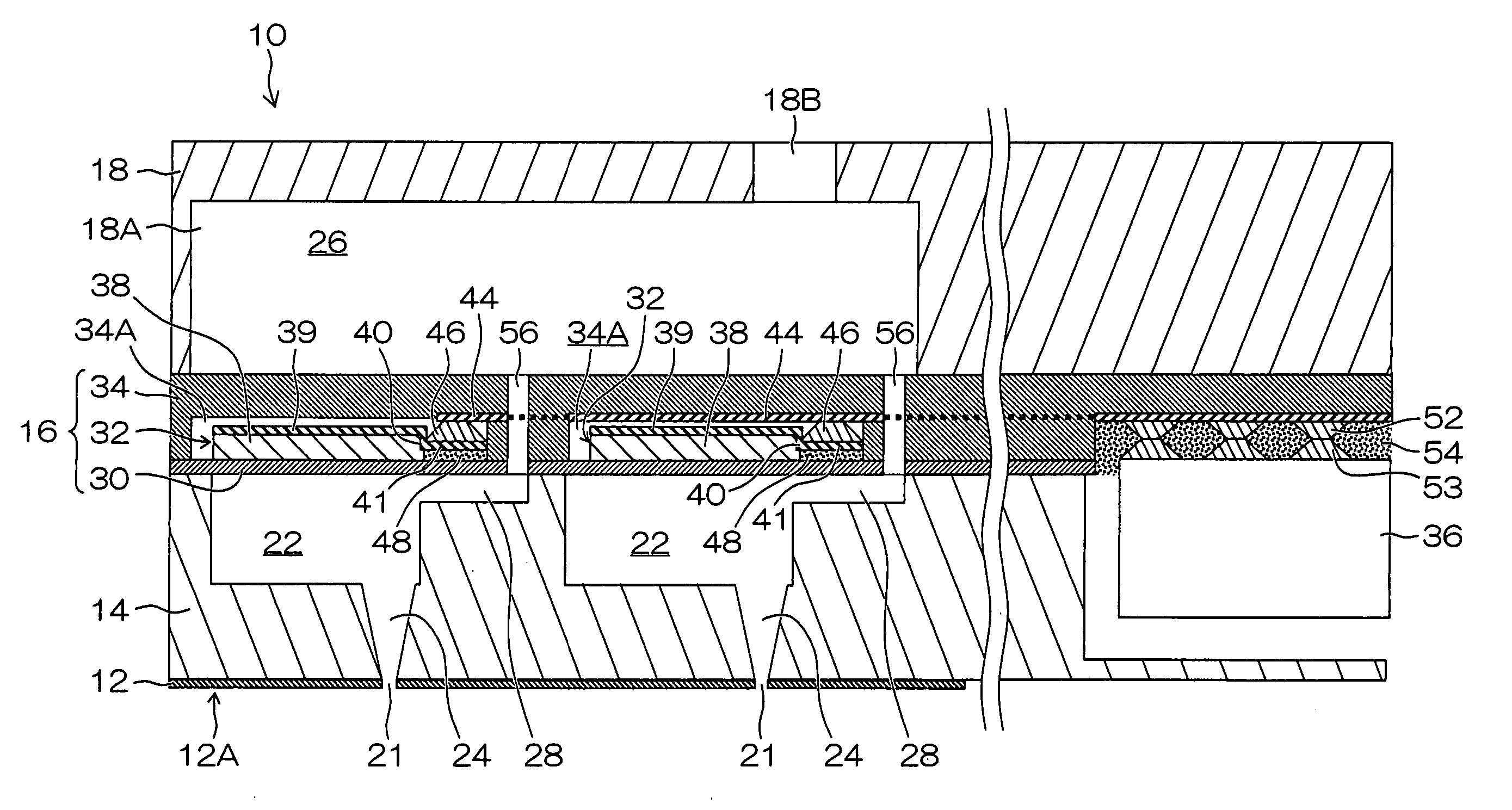
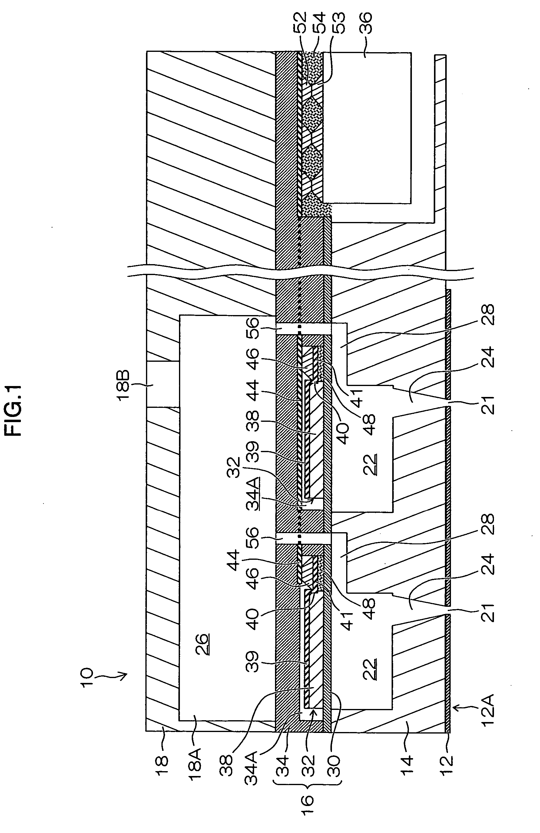
[0051] First of all, a constructional embodiment of an inkjet head (corresponding to the “liquid ejection head”) which is produced through the method of manufacturing a liquid ejection head according to an embodiment of the present invention, is described.

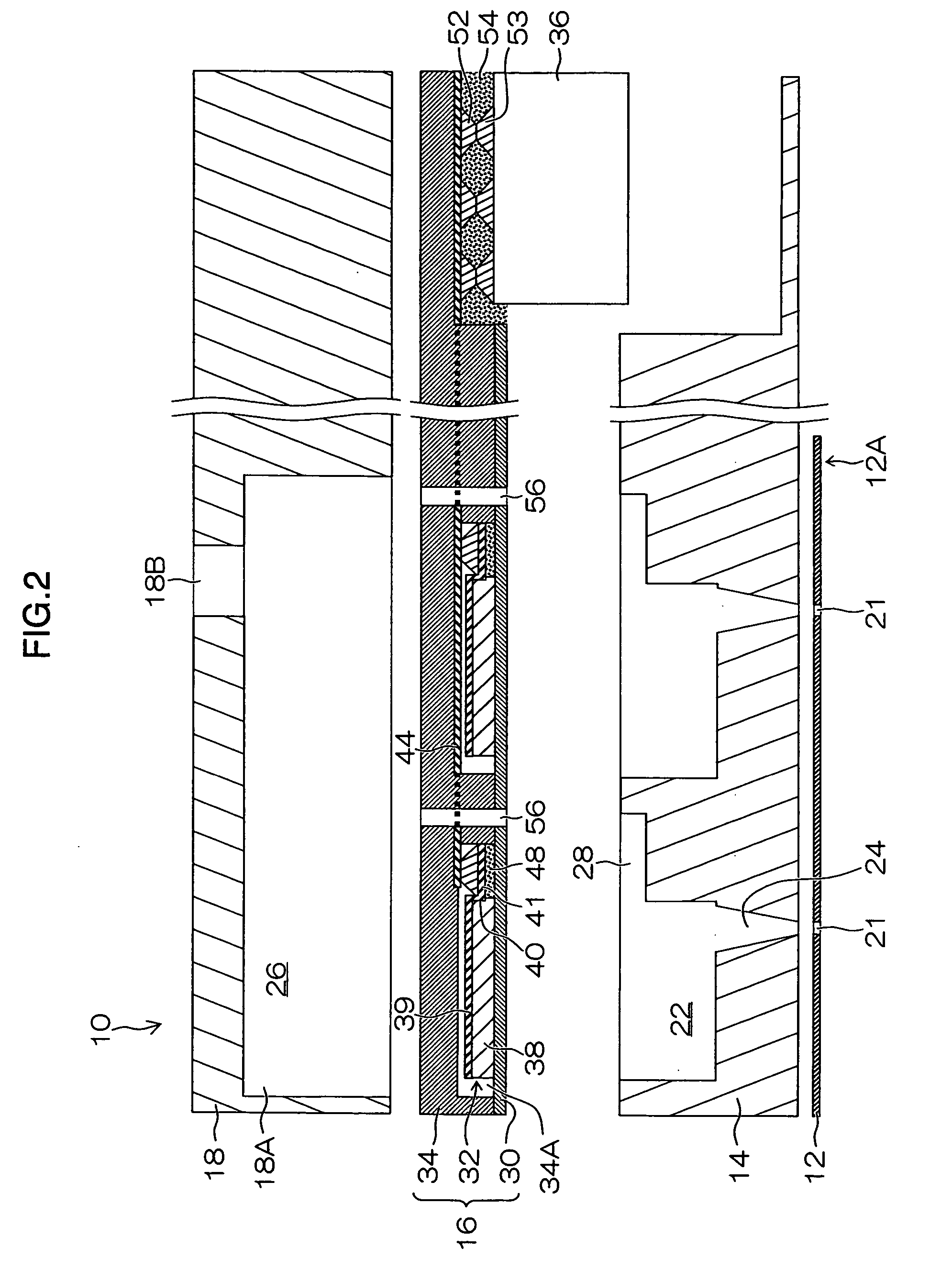
[0052]FIG. 1 is a cross-sectional view showing a structure of the inkjet head according to the present embodiment. FIG. 2 is an exploded view showing the elements of components in an understandable manner.

[0053] As shown in FIGS. 1 and 2, the inkjet head 10 according to the present embodiment is constituted from a layer structure in which a nozzle plate 12, a pressure chamber forming member (corresponding to the “flow path forming member”) 14, an actuator function unit 16, and an ink pool forming member (corresponding to the “flow path forming member” and “common liquid chamber forming member”) 18 are bonded to one another.

[0054] A plurality of holes of nozzles 21, which corre...


PUM

PropertyMeasurementUnit
temperatureaaaaaaaaaa
widthaaaaaaaaaa

Abstract

The method of manufacturing a liquid ejection head comprises the steps of: forming a plurality of piezoelectric elements on a diaphragm; stacking an intermediate plate which includes recess sections for covering the piezoelectric elements and drive wires connected to the piezoelectric elements, on a surface of the diaphragm on which the piezoelectric elements are formed, in such a manner that peripheral spaces are formed around the piezoelectric elements by means of the recess sections and electrical connections are created between the drive wires and the piezoelectric elements; connecting an integrated circuit to end sections of the drive wires which are opposite to connection sections between the drive wires and the piezoelectric elements; forming an actuator function unit by electrically and mechanically bonding the diaphragm, the piezoelectric elements, the drive wires, the intermediate plate and the integrated circuit after the formation of the piezoelectric elements on the diaphragm, the stack of the intermediate plate on the diaphragm, and the connection of the integrated circuit and the drive wires, in such a manner that the piezoelectric elements are electrically driven via the integrated circuit; measuring displacement of the diaphragm by operating the integrated circuit in the actuator function unit; and bonding a flow path forming member to the actuator function unit after the measurement of the displacement of the diaphragm, the flow path forming member being provided for forming a plurality of pressure chambers connected to a plurality of nozzles and forming a common liquid chamber for storing liquid supplied to the pressure chambers.

Description

BACKGROUND OF THE INVENTION [0001] 1. Field of the Invention [0002] The present invention relates to a method of manufacturing a liquid ejection head, and an image forming apparatus. In particular, the present invention relates to a method of manufacturing a liquid ejection head in which a plurality of liquid ejection ports (nozzles) are two-dimensionally arranged densely, and to an image forming apparatus, such as an inkjet recording apparatus, which can form an image on a recording medium by using such a liquid ejection head. [0003] 2. Description of the Related Art [0004] An inkjet recording apparatus causes ink droplets to be deposited on a recording medium by, in response to an image signal, ejecting inks from a recording head (print head) provided with nozzles for ink ejection, while relatively moving the recording head and the recording medium, and thereby an image is formed by means of thus obtained ink dots. [0005] A general recording head has a structure for supplying inks...

Claims


Application Information

Patent Timeline
Patent Type & Authority Applications(United States)
IPC IPC(8): B41J2/045
CPCB41J2/161B41J2/1623B41J2002/14241B41J2002/14459Y10T29/42B41J2202/20B41J2202/21Y10T29/49004Y10T29/49401B41J2002/14491
Inventor OKU, SEIICHIRO
Owner FUJIFILM CORP
Why Eureka
Try Eureka