Plasma display panel and method of driving the same

a technology of plasma display panel and display panel, which is applied in the direction of static indicating devices, instruments, and address electrodes, etc., can solve the problems of shortening the life deteriorating etc., and achieve the effect of reducing the “deterioration in the operating margin of the pdp devi

Inactive Publication Date: 2005-08-02
FUJITSU HITACHI PLASMA DISPLAY LTD
View PDF4 Cites 12 Cited by
  • Summary
  • Abstract
  • Description
  • Claims
  • Application Information

AI Technical Summary

Benefits of technology

[0026]The present invention has been made in view of the above circumstances, and an object of the present invention is to provide a plasma display panel adapted to reduce “deterioration in operating margin of a plasma display panel device”, the deterioration being caused with time by “variations with time in characteristics of a protective layer 14 surface of the plasma display panel”, as well as a method of driving the plasma display panel.
[0028]To achieve the aforementioned object, a second group of inventions according to the present application drive the PDP such that the sustain discharges have at least two discharge intensity values and the discharge intensity values are changed periodically. Driving the plasma display panel in such a manner causes decrease of the amount, to be sputtered during the sustain discharge (the surface discharge), of the portion of the protective layer on the Y electrode, the portion of the protective layer being straightforwardly involved in the address discharge, for reducing variations in characteristics of the address discharge (the opposite discharge).

Problems solved by technology

“Variations in characteristics (variations in voltage) of the address discharge 202” lead to gradual deterioration in operating margin of the PDP device.
Deterioration in operating margin finally shortens the life of the PDP device.

Method used


Image

  • Plasma display panel and method of driving the same
  • Plasma display panel and method of driving the same
  • Plasma display panel and method of driving the same

Examples


embodiments

Embodiment 1

[0063]Referring to FIGS. 3(a), 3(b) and 3(c), a driving method according to Embodiment 1 will be explained.

[0064]FIGS. 3(a) and 3(b) show driving waveforms of voltages applied to the X electrode and the Y electrode, respectively, for generating sustain discharges.

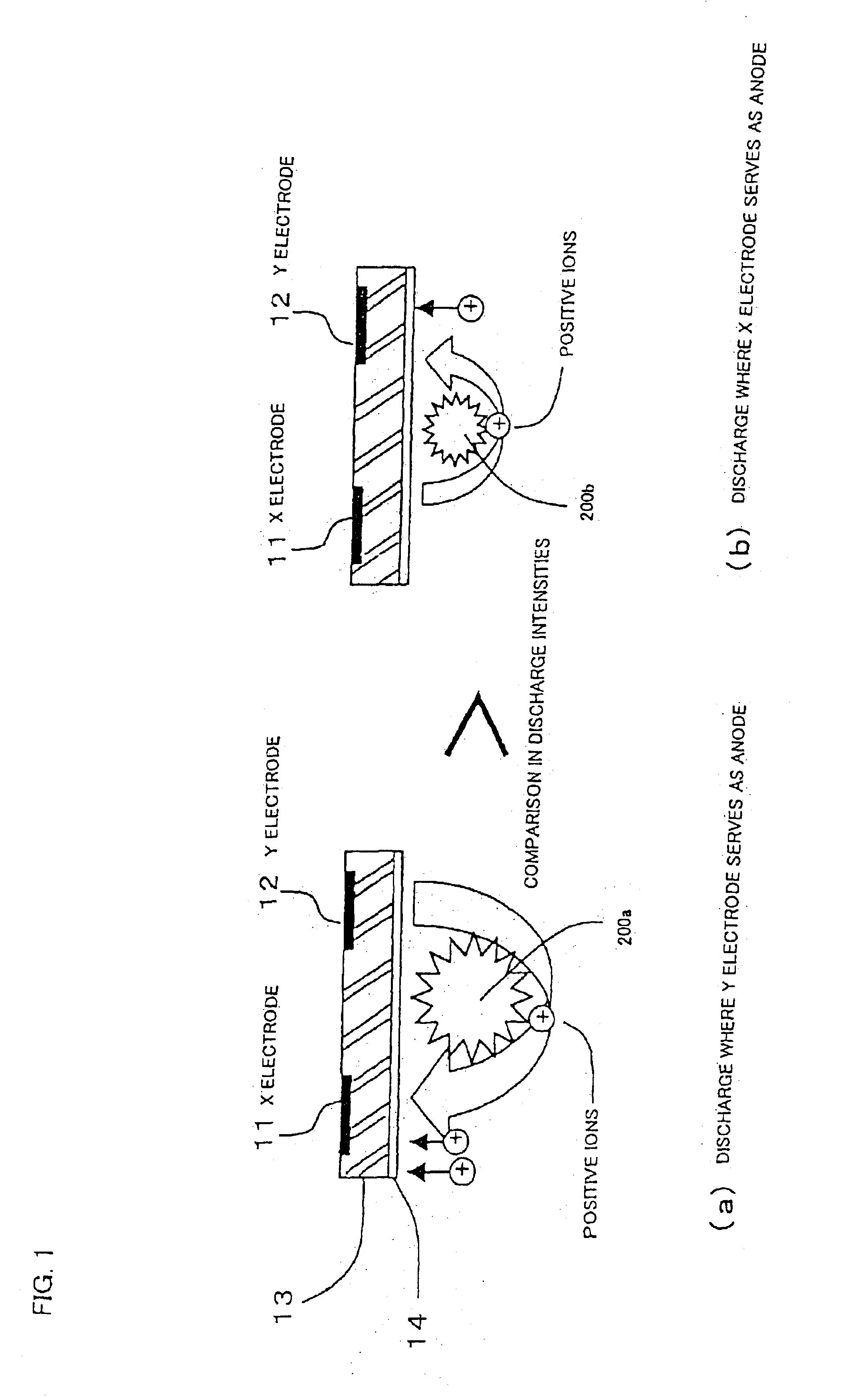
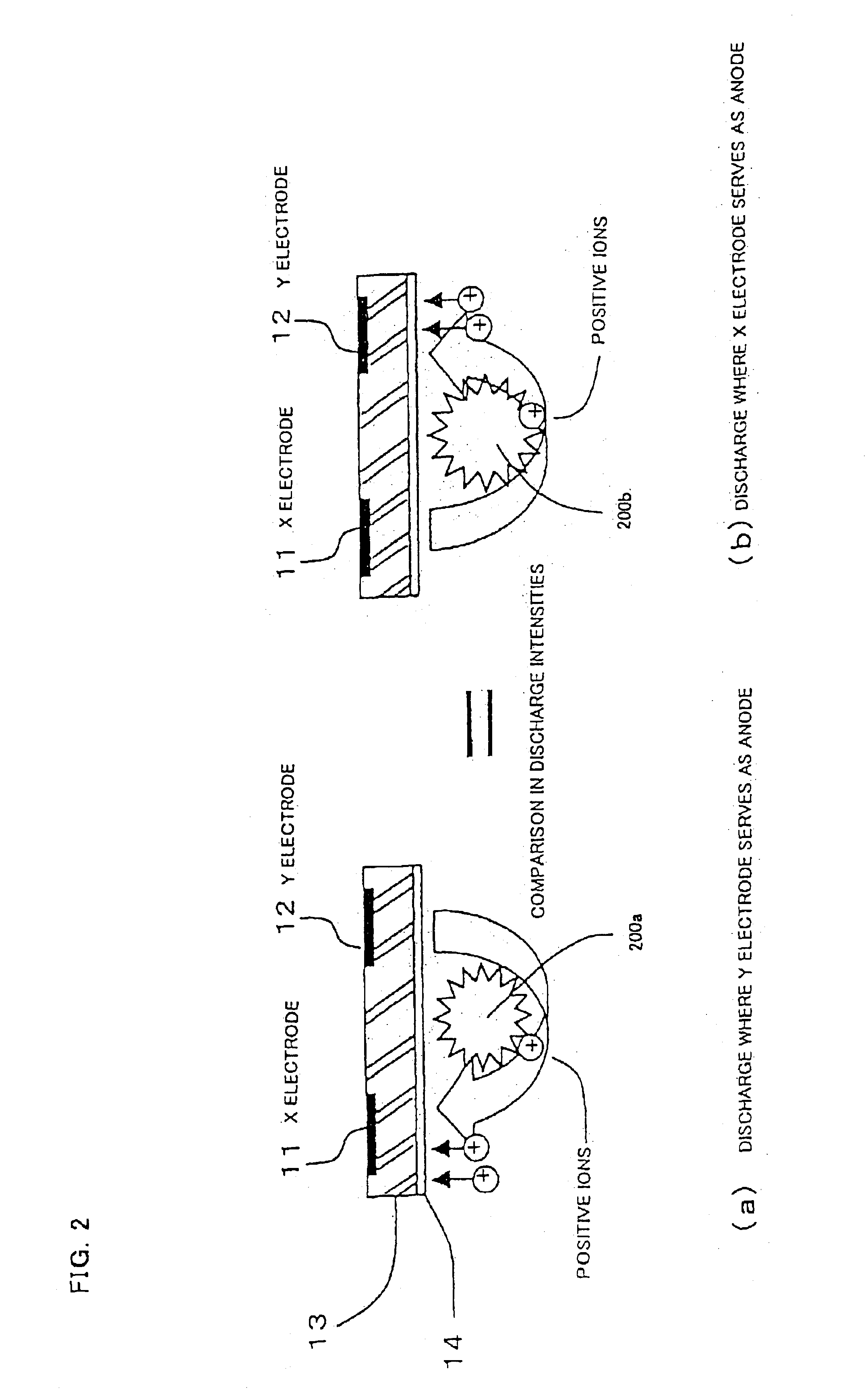
[0065]In a sustain discharge of a PDP, a discharge intensity becomes larger with the increase of a sustain voltage. For this reason, by reducing a sustain voltage (i.e., a crest value of a sustain pulse) Vs(X) applied to the sustain electrode (the X electrode) to a smaller value than that of a sustain voltage (i.e., a crest value of a sustain pulse) Vs(Y) applied to the scan electrode (the Y electrode), it is possible to reduce the instantaneous discharge intensity of a sustain discharge in which the sustain electrode serves as the anode to a smaller value than the value of the instantaneous discharge intensity of a sustain discharge in which the scan electrode serves as the anode. As a result, it is possible to...

embodiment 2

[0073]FIG. 5(a) shows driving waveforms and FIG. 5(b) shows discharge states in a cell, according to Embodiment 2.

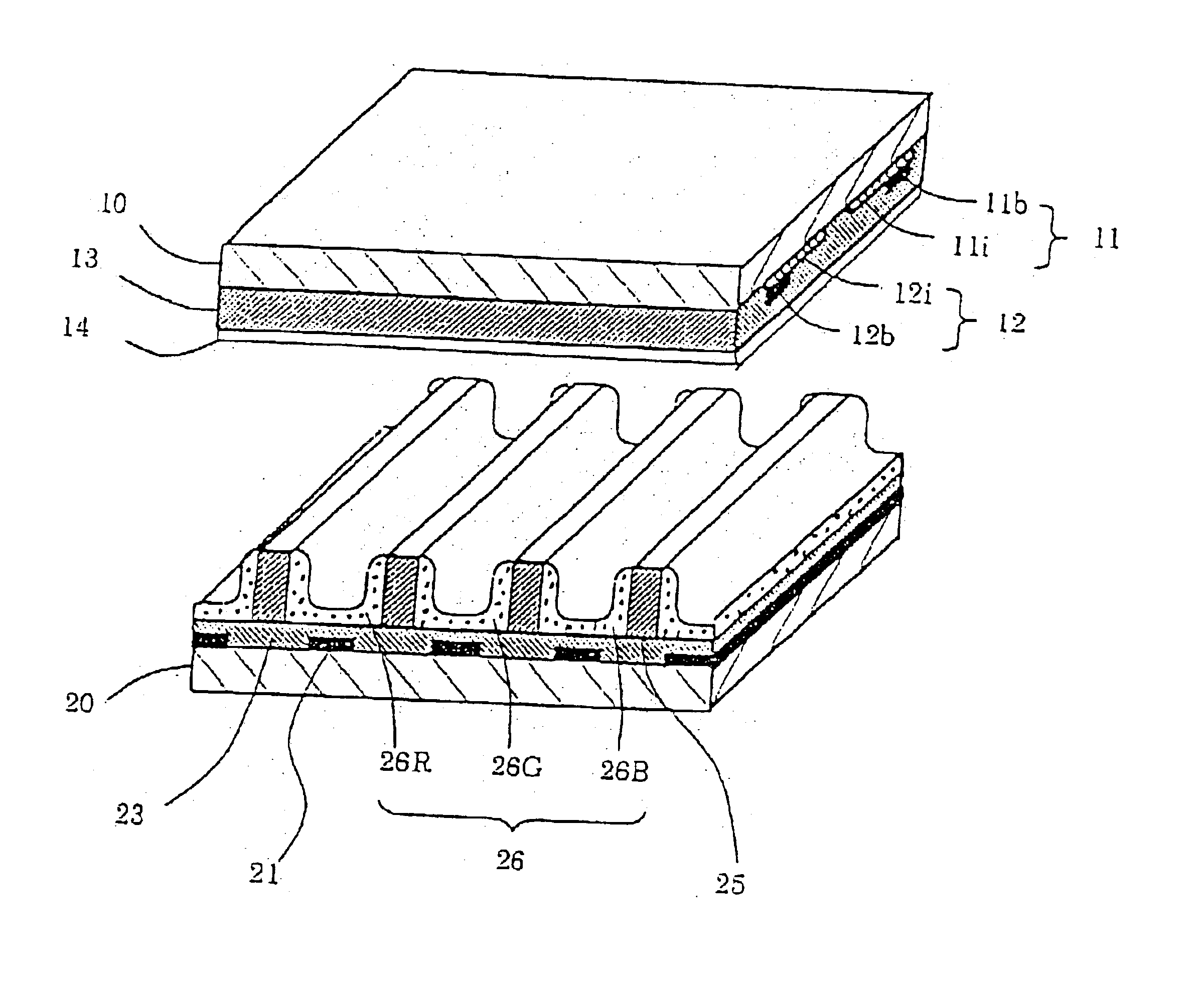
[0074]In FIG. 5(b), the X electrode 11, Y electrode 12 and A electrode 21 of FIG. 10 are indicated by symbols X, Y and A, respectively.

[0075]FIG. 5(b) shows the discharge states in the cell in steps {circle around (1)}-{circle around (4)} that correspond to steps {circle around (1)}-{circle around (4)} of the light emission profile of FIG. 5(a). In FIG. 5(b), illustrations are omitted of the front substrate (the substrate having the X electrode and the Y electrode), the dielectric layer on the address electrode on the rear substrate, and phosphor above the address electrode.

[0076]A discharge intensity of a sustain discharge is greatly affected by an amount of electric charge accumulated in a cell at the time immediately before the sustain discharge. The accumulation of the amount of electric charge is completed at the end of the immediately preceding sustain discharge.

[0...

embodiment 3

[0087]Referring to FIGS. 6(A), 6(B), 6(C) and 6(D), a driving method according to Embodiment 3 will be explained.

[0088]FIGS. 6(B), 6(C) and 6(D) show driving waveforms applied to the X electrode, the Y electrode and the A electrode, respectively, for generating the sustain discharge, and FIG. 6(A) shows the light emission profile.

[0089]This embodiment is the same as Embodiment 2 except for the driving waveform of the address electrode 21.

[0090]To the address electrode 21, an address voltage Va is applied during a period of occurrence of the auxiliary discharge 211 and during the period subsequent to that, and a voltage at a ground level (0V) is applied during the other periods. Thus, the voltage of positive charge is applied to the address electrode 21 when the auxiliary discharge 211 should occur for facilitating occurrence of the auxiliary discharge 211. This can be easily understood if reference is made to an orientation (a direction indicated by arrow) of the auxiliary discharge...


PUM


Abstract

A driving method of the present invention is adapted to a plasma display panel which includes first and second electrodes formed on a substrate, third electrodes formed in a direction intersecting the first and second electrodes, and a dielectric layer covering the first and second electrodes. The driving method includes the steps of generating an address discharge between the first and the third electrode to select a predetermined cell and sustain discharges between the first and the second electrode to produce light for display, and controlling the plasma display panel such that the discharge intensity of a sustain discharge in which the second electrode serves as the anode is smaller than the discharge intensity of a sustain discharge in which the first electrode serves as the anode.

Description

CROSS-REFERENCE TO RELATED APPLICATION[0001]This application is related to Japanese application JP2002-072648, filed on Mar. 15, 2002, whose priority is claimed under 35 USC §119, the disclosure of which is incorporated by reference in its entirety.BACKGROUND OF THE INVENTION[0002]1. Field of the Invention[0003]The present invention relates to a plasma display panel and a method of driving it. More particularly, it relates to a plasma display panel adapted to reduce deterioration in operating margin of a plasma display panel device, the deterioration being caused with time by variations with time in characteristics of a protective layer surface of the plasma display panel, and to a method of driving the plasma display panel.[0004]2. Description of the Related Art[0005]Conventionally, plasma display panels as gas discharge display devices have been used for display terminals on the TV, computer or like. Recently, a number of producers and universities have actively conducted research...

Claims


Application Information

Patent Timeline
Patent Type & Authority Patents(United States)
IPC IPC(8): G09G3/28G09G3/20G09G3/291G09G3/294G09G3/296G09G3/298H01J11/12H01J11/14H01J11/20H01J11/22H01J11/24H01J11/26H01J11/34H01J11/38
CPCG09G3/294G09G3/2983G09G3/2018G09G2310/06G09G2310/066G09G2320/0228G09G2320/043G09G2320/046H01J2211/245G09G3/296H01J11/20
Inventor KAWASAKI, TATSUHIKOSASAKI, TAKASHI
Owner FUJITSU HITACHI PLASMA DISPLAY LTD
Why Eureka
Try Eureka