Device for generating X-rays

a technology for generating devices and x-rays, applied in nuclear engineering, x-ray tube targets and convertors, x-ray tube target materials, etc., can solve the problem of limited liquid metal pressure and the lik

Inactive Publication Date: 2005-08-02
KONINKLIJKE PHILIPS ELECTRONICS NV
View PDF6 Cites 24 Cited by
  • Summary
  • Abstract
  • Description
  • Claims
  • Application Information

AI Technical Summary

Benefits of technology

[0004]An object of the invention is to provide a device for generating X-rays of the kind mentioned in the opening paragraph in which the necessary pressure of the liquid metal is limited, so that the above mentioned disadvantages are avoided as much as possible.

Problems solved by technology

Since the liquid metal flow in the impingement position is thus achieved by means of viscous shear forces and not by means of a pressure of the liquid metal upstream of the impingement position, the necessary pressure of the liquid metal is limited.
The necessary pressure of the liquid metal is mainly determined by the pressure losses in the heat exchanger, which can be limited by suitable dimensions of the heat exchanger.

Method used


Image

  • Device for generating X-rays
  • Device for generating X-rays
  • Device for generating X-rays

Examples


first embodiment

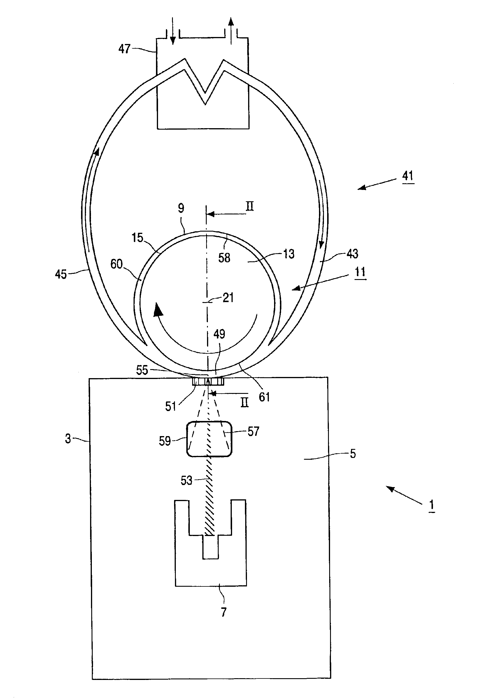
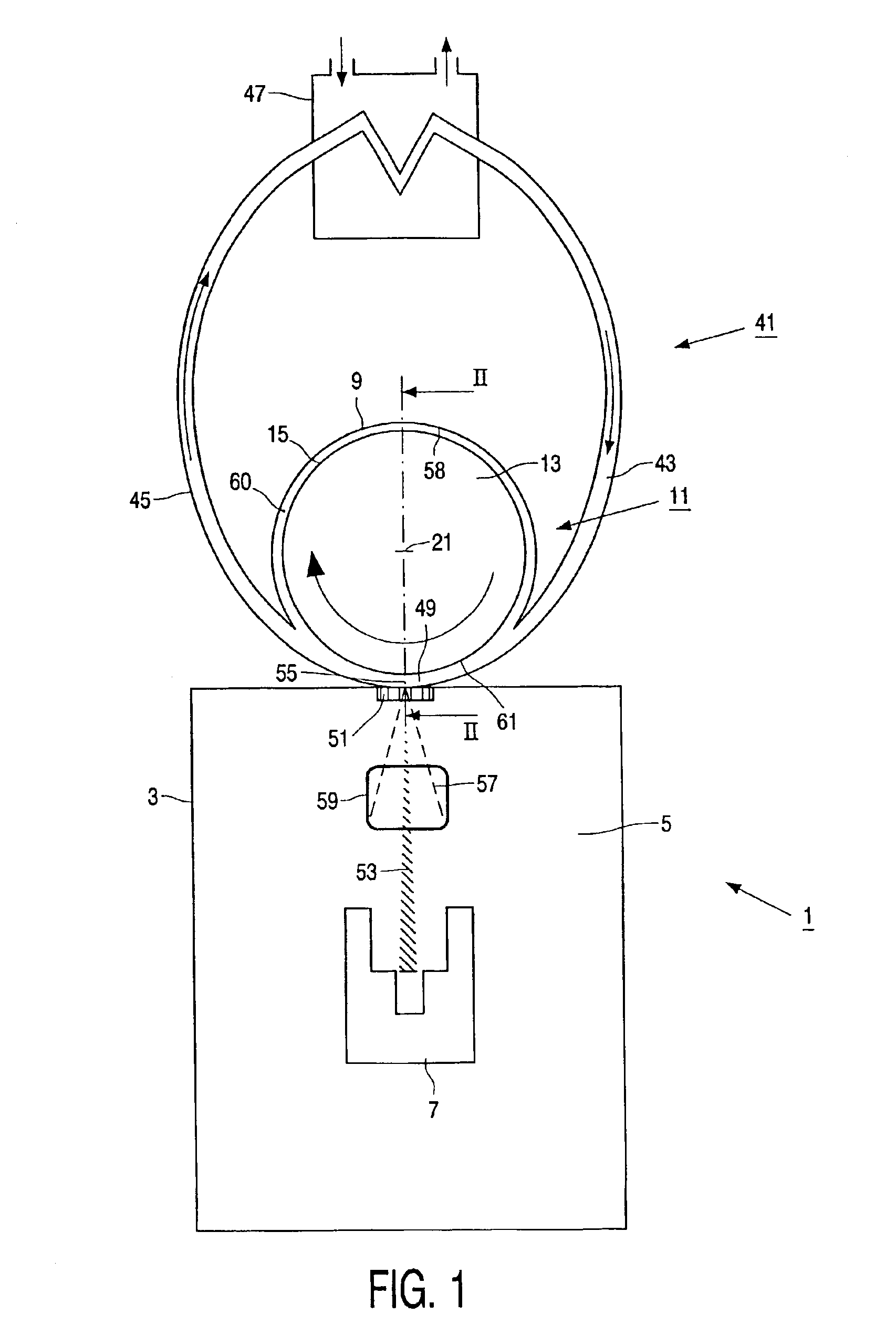
[0026]As schematically shown in FIG. 1, a device 1 for generating X-rays according to the invention comprises a housing 3 enclosing a vacuum space 5 in which a source 7 or cathode for emitting electrons is present. The device 1 further comprises a closed circular-cylindrical chamber 9 which is mounted to the housing 3 in a manner which is not further disclosed in detail. In said chamber 9, a displacing member 11 is present comprising a carrier 13, in the embodiment shown comprising a closed cylinder, having a circular-cylindrical outer surface 15. As shown in FIG. 2, the carrier 13 is journalled by means of dynamic groove bearings 17, 19 relative to the chamber 9 so as to be rotatable about a central axis 21 of the outer surface 15. The dynamic groove bearings 17, 19 are of a kind which is known per se, and are each provided with a radial bearing part 23, 25 for generating bearing forces in a radial direction and with an axial bearing part 27, 29 for generating bearing forces in an ...

second embodiment

[0031]In FIG. 4 parts of a device 101 for generating X-rays according to the invention, which correspond to parts of the device 1 as shown in FIGS. 1-3, are indicated with corresponding reference numbers. In the following, the differences between the devices 1 and 101 will be discussed. In the device 101, the housing 3′ accommodating the source 7′ is mounted to a substantially circular-cylindrical closed chamber 103 having a central axis 105 and comprising a first main inner surface 107 and a second main inner surface 109, which extend substantially perpendicularly to the central axis 105, and a circular-cylindrical circumferential inner surface 111. In the chamber 103 a displacing member 113 is present, which comprises a substantially disc-shaped carrier 115 having a first main outer surface 117, which extends substantially parallel to the first main inner surface 107 of the chamber 103, a second main outer surface 119, which extends substantially parallel to the second main inner ...

third embodiment

[0039]In FIG. 6 parts of a device 201 for generating X-rays according to the invention, which correspond to parts of the device 1 as shown in FIGS. 1-3, are indicated with corresponding reference numbers. In the following, the differences between the devices 1 and 201 will be discussed. An important difference is that the device 201 has an impingement position 203 in which the liquid metal is not separated from the vacuum space 5″ by means of an X-ray and electron transparent window, like in the devices 1 and 101, but in which the liquid metal has a free surface 205 in the vacuum space 5″. Contamination of the vacuum space 5″ by the liquid metal is prevented in a manner which will be discussed hereinafter. Due to the absence of an X-ray and electron transparent window in contact with the liquid metal, which window usually is rather fragile, the risk of malfunction of the device 201 is considerably reduced.

[0040]The device 201 comprises a displacing member 207 which, for the greater ...


PUM


Abstract

The invention relates to a device (1) for generating X-rays (57). The device comprises a source (7) for emitting electrons (53) and a liquid metal for emitting X-rays as a result of the incidence of electrons. The device further comprises a displacing member (11) for displacing the liquid metal through an impingement position (55) where the electrons emitted by the source impinge upon the liquid metal. As a result of the flow of liquid metal through the impingement position the heat, which is generated in the impingement position as a result of the incidence of the electrons upon the liquid metal, is transported away from the impingement position.
According to the invention, the displacing member (11) has a contact surface (61), which is in contact with the liquid metal in the impingement position (55), and a driving member (31) for moving the contact surface in a direction which, in the impingement position, is substantially parallel to the contact surface. Thus the flow of liquid metal in the impingement position is achieved as a result of viscous shear forces in the liquid metal caused by friction forces between the liquid metal and the moving contact surface. As a result, the necessary pressure of the liquid metal is limited.

Description

BACKGROUND[0001]The invention relates to a device for generating X-rays, which device comprises a source for emitting electrons, a liquid metal for emitting X-rays as a result of the incidence of electrons, and a displacing member for displacing the liquid metal through an impingement position where the electrons emitted by the source impinge upon the liquid metal.[0002]A known device for generating X-rays is described in U.S. Pat. No. 6,185,277-B1. During operation of the known device, the liquid metal, e.g. mercury, flows through a narrow passage which forms part of a closed cyclical channel system. Said narrow passage is bounded by a relatively thin window made from a material which is transparent to X-rays and electrons, e.g. diamond. The window separates the liquid metal from a vacuum space in which the source is accommodated. The source generates an electron beam, which passes through the window and impinges upon the liquid metal in the impingement position behind the window. ...

Claims


Application Information

Patent Timeline
Patent Type & Authority Patents(United States)
IPC IPC(8): H01J35/08H01J35/00H01J35/10
CPCH01J35/08H01J2235/082
Inventor HARDING, GEOFFREYDAVID, BERNDSCHLOMKA, JENS PETERTIELEMANS, LEONARDUS PETRUS MARIAPOTZE, WILLEM
Owner KONINKLIJKE PHILIPS ELECTRONICS NV
Why Eureka
Try Eureka