Method and apparatus for correcting resolver output

a resolver and output technology, applied in the direction of electronic commutators, ac/dc measuring bridges, instruments, etc., can solve the problems of increasing the cost of time, cost and effort, and the accuracy of detecting the rotational angle is affected, so as to improve the detection accuracy of the rotational angle of the rotating devi

Inactive Publication Date: 2005-08-02
DENSO CORP
View PDF13 Cites 17 Cited by
  • Summary
  • Abstract
  • Description
  • Claims
  • Application Information

AI Technical Summary

Benefits of technology

[0009]The present invention therefore has an object to provide a method an...

Problems solved by technology

However, an amount of the magnetic flux changes over time, and the resolvers have variations in the amount of the magnetic flux during manufacturing.
This results in worsening accuracy of dete...

Method used


Image

  • Method and apparatus for correcting resolver output
  • Method and apparatus for correcting resolver output
  • Method and apparatus for correcting resolver output

Examples


Embodiment Construction

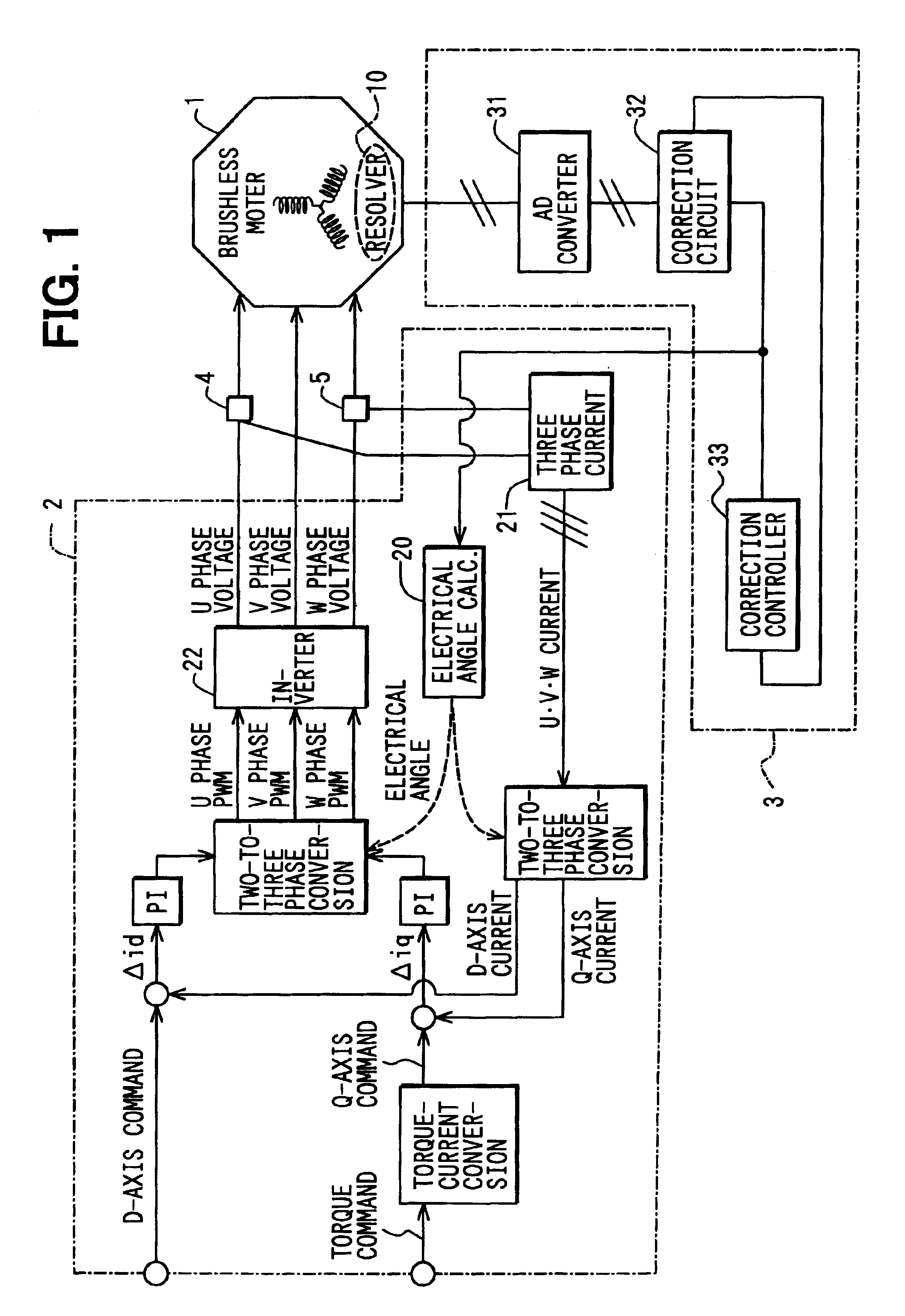
[0017]The preferred embodiments of the present invention will be explained with reference to the accompanying drawings. Referring to FIG. 1, a motor control system includes a brushless motor 1, a motor control device 2, a resolver output correction device 3, and current sensors 4, 5. The brushless motor 1 has a built-in resolver 10. The resolver output correction device 3 produces corrected output signals. The current sensors 4, 5 measure electric currents and produce current data relating to the electric currents.

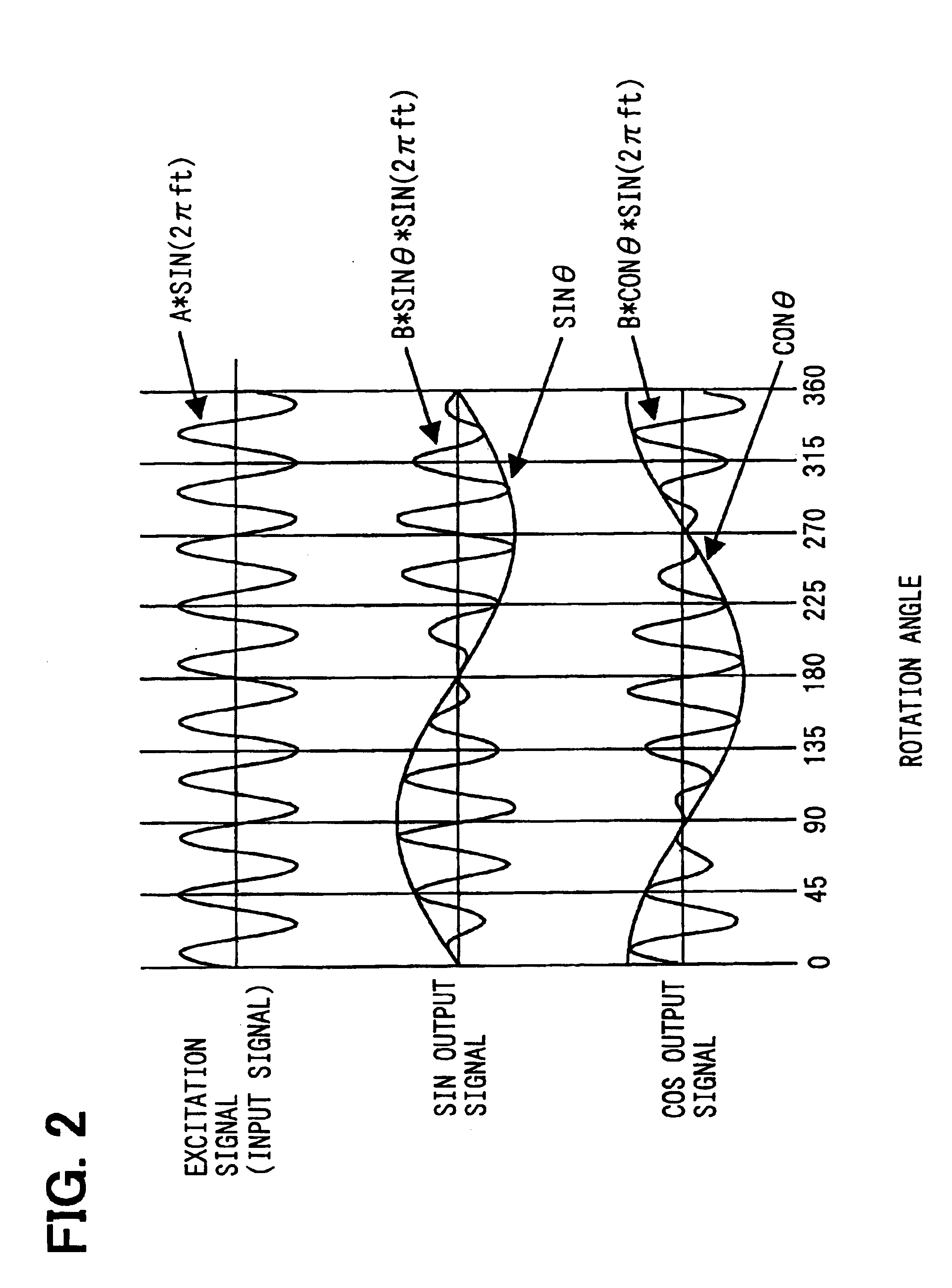
[0018]The resolver 10 has a rotor that is fixed to a rotary shaft of the motor 1, and a stator that surrounds the rotor. A couple of output windings, which are electrically shifted by angle n / 2 from each other, are wound around the stator. The couple of output windings produce sine wave output signal and cosine wave output signal. A carrier voltage is energized to excitation windings of the motor 1. Referring to FIG. 2, the sine wave output signal is the product of the car...


PUM


Abstract

A resolver output correction device receives sine output signal and cosine output signal from a resolver. Each of the sine output signal and the cosine output signal has an offset error and a gain differential error due to a secular variation. The correction device detects maximal and minimal values with respect to both the sine output signal and the cosine output signal. It calculates average values between the maximal values and the minimal values. Then, it corrects the offsets of the signals based on the average values. It also calculates gain differentials between the maximal value and the minimal value with respect to both the sine and cosine signals. Then, it corrects the gain differentials of the signals based on the calculated gain differentials. As a result, both the offset and gain errors of the signals are corrected with accuracy.

Description

REFERENCE TO RELATED APPLICATIONS[0001]This application is based on Japanese Patent Application No. 2002-204665 filed on Jul. 12, 2002, the contents of which are incorporated herein by reference.BACKGROUND OF THE INVENTION[0002]1. Field of the Invention[0003]The present invention relates to a method and an apparatus for correcting a resolver output, more particularly to correcting an offset error and a gain error of the resolver output.[0004]2. Description of Related Art[0005]Resolvers are rotational angle sensors that are commonly used for sensing rotational angles of rotary devices, such as engines and vehicular motors. The resolvers have windings for producing magnetic flux linked to the windings. However, an amount of the magnetic flux changes over time, and the resolvers have variations in the amount of the magnetic flux during manufacturing. This results in worsening accuracy of detecting the rotational angle.[0006]In detail, the resolver produces a sine output signal and a co...

Claims


Application Information

Patent Timeline
IPC IPC(8): G01D3/02G01D5/12G01D18/00G01D5/20H02P6/14H02P6/16G01D5/245H02P6/06H02P6/08H02P6/28H02P29/00
CPCG01D3/02G01D3/022G01D5/2073G01D18/008H02P6/165H02P21/00H02P6/17
Inventor KAMEYA, HISASHI
Owner DENSO CORP
Why Eureka
Try Eureka