
Disc cartridge

a technology of disc cartridges and cartridge bodies, applied in the field of disc cartridges, can solve the problems of omission of optical discs in recording and/or reproduction of data signals, affecting and affecting the appearance of the outer appearance, so as to facilitate the identification of disc cartridges and prevent damage to the cartridge body

Inactive Publication Date: 2005-08-02
SONY CORP
View PDF25 Cites 3 Cited by
  • Summary
  • Abstract
  • Description
  • Claims
  • Application Information

AI Technical Summary

Benefits of technology

[0022]An object of the present invention is to provide a disc cartridge able to accommodate disk-like recording media of different types having a common size which facilitates the identification of the disc cartridges having a generally common shape and can prevent damage to the cartridge body even in a case where the disc cartridge is loaded in an unsuitable recording and / or reproducing apparatus.
[0023]Another object of the present invention is to provide a disc cartridge which enables reliable joining of the upper half and the lower half of the cartridge body by using the ultrasonic welding method.
[0024]Still another object of the present invention is to provide a disc cartridge which enables reliable joining of the upper half and the lower half of the cartridge body while shortening the time of applying the ultrasonic wave.
[0025]Further another object of the present invention is to provide a disc cartridge which enables joining of the upper half and the lower half by using the ultrasonic welding method without detracting from the outer appearance of the cartridge body.

Problems solved by technology

Further, there also exists a concern that, due to the application of an ultrasonic wave over a long time, the optical disc will vibrate in the cartridge body, rubbing will occur between the optical disc and the walls forming the portion accommodating the recording medium constituting the disc accommodating portion, and the optical disc will be scratched or shaving powder will be generated.
When the shaving powder is generated and adhers to the signal recording portion, there also exists a concern of occurrence of the omissions in the recording and / or reproduction of the data signal.
In this way, in a disc cartridge accommodating an optical disc or magnetic disc of a diameter of 3.5 inch, it becomes extremely difficult to distinguish the two from the outer appearance.
For this reason, there also exists a concern over erroneous loading, for example, erroneously loading a disc cartridge accommodating an optical disc of a diameter of 3.5 inches or a disc cartridge accommodating a magnetic disc of a diameter of 3.5 inch in the recording and / or reproducing apparatus.
Further, in a recording and / or reproducing apparatus using a disc cartridge accommodating an optical disc as the recording medium and a recording and / or reproducing apparatus using a disc cartridge accommodating a magnetic disc as the recording medium, the recording and / or reproduction means are completely different, so if the cartridges are erroneously loaded in the apparatuses, there is a concern that not only will the recording and / or reproduction of the data signal not be carried out, but also the recording and / or reproduction means such as the optical pick-up or the magnetic head provided on the recording and / or reproducing apparatus side will be damaged.
In a disc cartridge wherein the type of the disc cartridge is identified and the loading of the same to an apparatus other than the suitable recording and / or reproducing apparatus is inhibited by providing the recess or engagement groove in one part of the cartridge body in this way, there is a concern that, if the disc cartridge is erroneously loaded in the recording and / or reproducing apparatus, the cartridge body will be damaged when the mechanism for preventing erroneous loading is engaged with the recess or engagement groove with which it should not originally be engaged.
Particularly, in a disc cartridge wherein the upper and lower halves are joined by ultrasonic welding, there is a concern that the upper and lower halves will come apart.

Method used


Image

  • Disc cartridge
  • Disc cartridge
  • Disc cartridge

Examples


Embodiment Construction

[0064]Below, the disc cartridge according to the present invention will be explained by referring to the drawings.

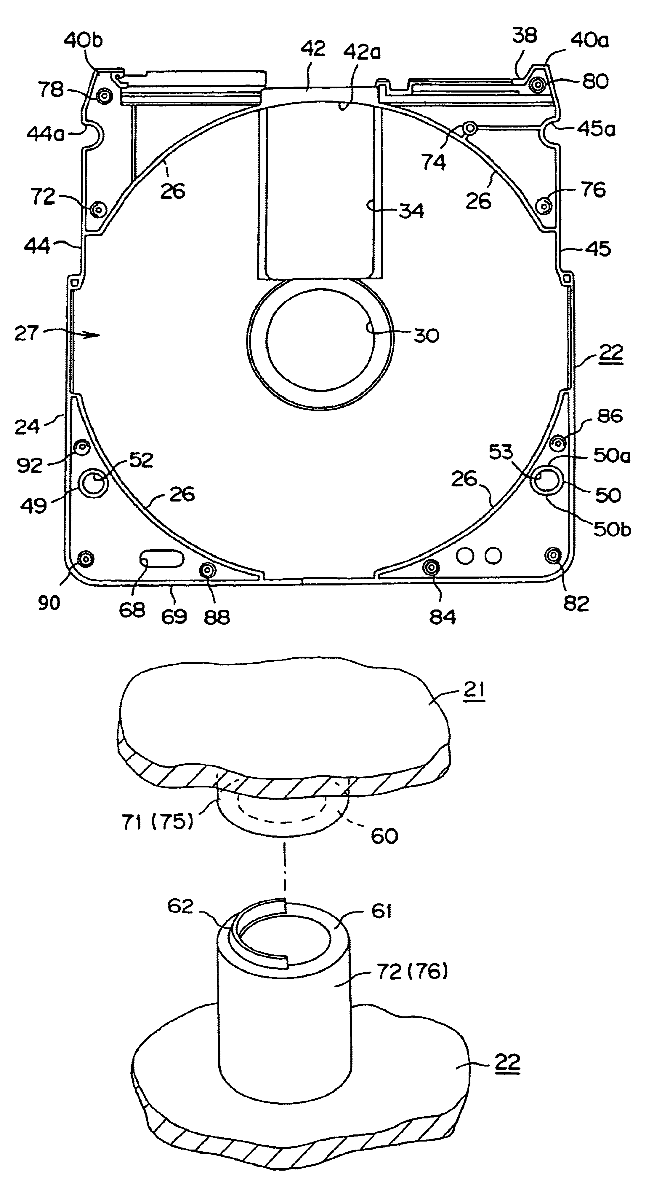
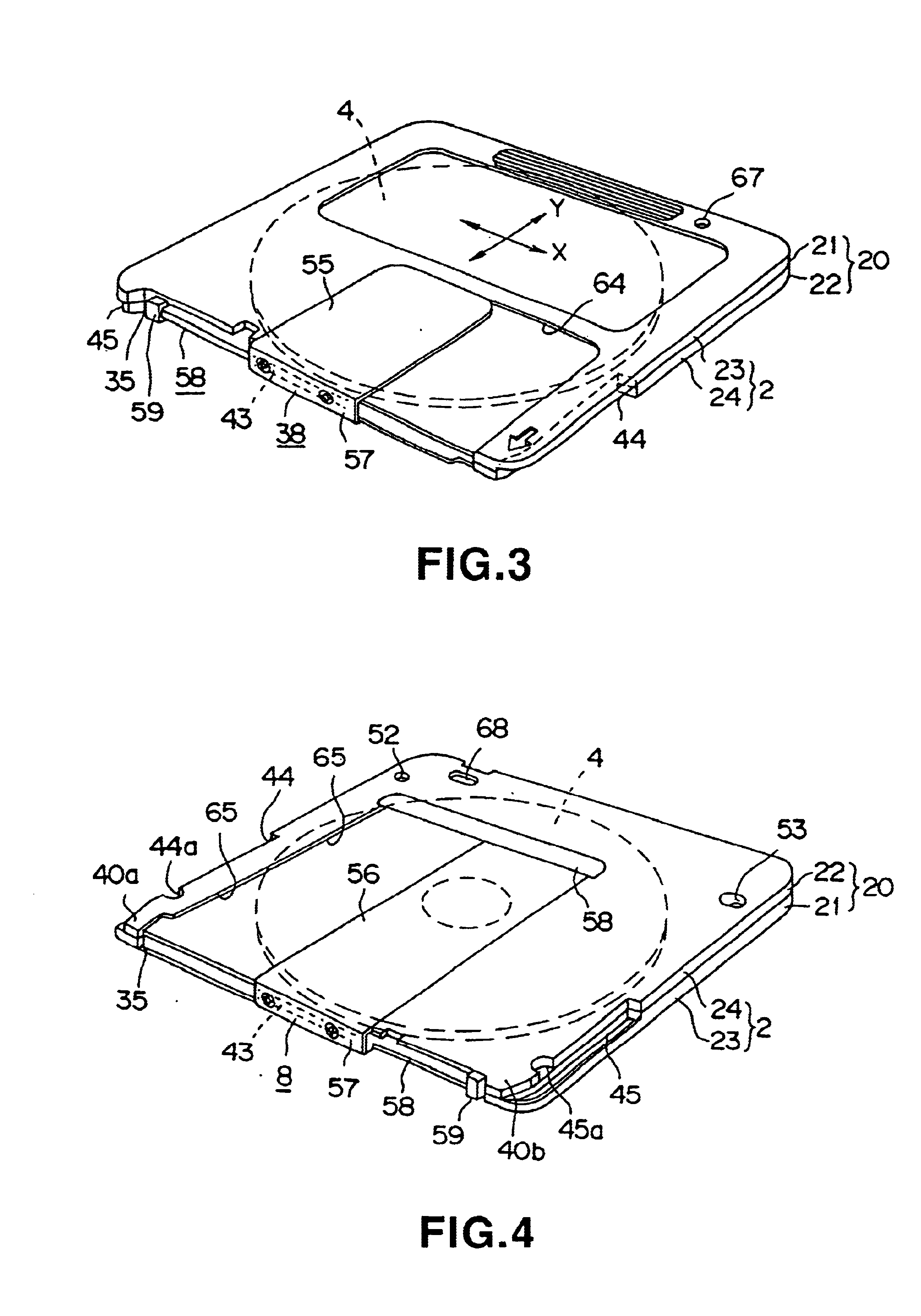
[0065]A disc cartridge 1 according to the present invention is constituted by providing a cartridge body 20 formed as shown in FIG. 3 and FIG. 4, by mating and joining an upper half 21 and a lower half 22 formed by shaping a plastic material into substantially shallow dish like rectangles and rotatably accommodating the optical disc 4 in this cartridge body 20.

[0066]The optical disc 4 accommodated in this disc cartridge 1 is formed to a diameter of 3.5 inch and, as shown in FIG. 5, is constituted by a disc substrate 4a exhibiting a disk shape and a hub 10 for magnet clamping attached so as to be fitted in a center hole 4b provided at the center of this disc substrate 4a.

[0067]To fabricate this optical disc 4, as is well known, a stamper is prepared by a mastering process including cutting of the original disk. Then, a plastic material having a light transmitting propert...


PUM

PropertyMeasurementUnit
diameteraaaaaaaaaa
diameteraaaaaaaaaa
areaaaaaaaaaaa

Abstract

A disc cartridge accommodating an optical disc in a cartridge body. This disc cartridge is provided with a cartridge body formed by mating and joining a pair of upper and lower halves formed at the circumferential edges with rising circumferential walls which are mated to each other to constitute the circumferential side walls and, at the same time, formed at facing inner surfaces with walls for forming the accommodating portion which are mated to each other to constitute the disc accommodating portion in which the optical disc is accommodated. This cartridge body is provided with openings for recording and reproduction and a shutter member for opening and closing these openings. On the two sides of the cartridge body on the lower half from the front side toward the middle toward the back side are provided recess portions for preventing erroneous loading. A plurality of fusing portions for mating and fusing the upper and lower halves are provided at positions corresponding to these recess portions.Each fusing portion for mating and fusing the upper and lower halves is provided with a mating projection formed at one of the upper and lower halves and a mating projection formed at the other. A plurality of mating projections formed at either half comprise mating projections having projections for fusing annularly and continuously formed over the entire circumference of the end surfaces to be mated to the mating projections of the other half and mating projections having projections for fusing formed in the form of an arc in one part of the end surfaces.

Description

FIELD OF THE INVENTION[0001]The present invention relates to a disc cartridge accommodating a disk-like recording medium such as an optical disc on which a data signal is recorded, more particularly relating to a disc cartridge in which a disk-like recording medium is accommodated in a cartridge body formed by placing together and connecting a pair of upper and lower halves formed by shaping a plastic material.BACKGROUND OF THE INVENTION[0002]Conventionally, a disc cartridge accommodating a disk recording medium such as an optical disc on which a data signal is recorded comprises a cartridge body formed by placing together and connecting a pair of upper and lower halves formed by shaping a plastic material such as an ABS resin and by accommodating the disk recording medium in this cartridge body so that it can rotate. The disc cartridge is mounted in a recording and / or reproducing apparatus in a state with the disk recording medium accommodated therein as it is. The disk recording m...

Claims


Application Information

Patent Timeline
Patent Type & Authority Patents(United States)
IPC IPC(8): G11B23/03
CPCG11B23/0316G11B23/0326G11B23/0308G11B23/03
Inventor KOBAYASHI, DAIKIFUNAWATARI, TAKATSUGUTAKAHASHI, KENJI
Owner SONY CORP
Learn More