Angular adjustment arrangement of pivot hinge

a technology of pivot hinge and adjustment arrangement, which is applied in the direction of door/window fittings, multi-purpose tools, construction, etc., can solve the problems of destroying the ornamental appearance of the glass door, the configuration of the glass door is too complicated for a skilled technician to be required for installation, and the installation of the skilled technician is required. , to achieve the effect of minimizing the manufacturing cost of the pivot hinge, minimizing the maintenance cost of the glass structure, and easy and simple alignment operation

Inactive Publication Date: 2005-08-09
CHEN MEI LI
View PDF17 Cites 39 Cited by
  • Summary
  • Abstract
  • Description
  • Claims
  • Application Information

AI Technical Summary

Benefits of technology

[0010]Another object of the present invention is to provide a pivot hinge for a glass structure, wherein the glass structure does not require to be unlocked or released from the angular adjustment arrangement in order to align with the border frame. In other words, the aligning operation is easy and simple that an individual is able to self-adjust the glass structure to align with the border frame, so as to minimize the maintenance cost of the glass structure.
[0011]Another object of the present invention is to provide a pivot hinge for a glass structure, wherein the pivot hinge is a universal hinge structure adapted to mount at the right, left, top, or bottom edge portion of the glass structure so as to minimize the manufacturing cost of the pivot hinge of the present invention in comparison with the conventional pivot hinge that must be made in pair.
[0012]Another object of the present invention is to provide a pivot hinge for a glass structure, wherein the pivot hinge further comprises a reinforcing member mounted at the frame track to increase the thickness thereof so as to enhance the strength of the frame track. Therefore, the engagement between the pivot hinge and the border frame can be substantially strengthened without altering the original structure of the frame track.
[0013]Another object of the present invention is to provide a pivot hinge for a glass structure, wherein no expensive or complicated structure is required to employ in the present invention in order to achieve the above mentioned objects. Therefore, the present invention successfully provides an economic and effective solution not only for providing a rigid configuration to securely mount the glass structure within the border frame but also for enhancing the angular adjustment of the glass structure to align with the border frame.
[0019]an angular adjustment locker provided at an outer side of the joint seat to securely lock up the supporting shaft within the adjustment sleeve in a rotatably movable manner for retaining an alignment of the glass structure in position with respect to the border frame so as to pivotally mount the glass structure to the border frame.

Problems solved by technology

However, such pivot hinge assembly has several drawbacks.
It is worth to mention that when the glass door is misalignedly mounted to the door frame, the ornamental appearance of the glass door will be destroyed or even the glass door cannot be closed.
In other words, the configuration of the glass door is too complicated that a skilled technician is required for the installation.
In addition, the relatively heavy weight of the glass door and the pivot movement thereof will cause the glass door to misalign with the door frame after a period of time.
However, the user is not able to self adjust the alignment of the glass door.
Therefore, the user must call the technician to fix the alignment of the glass door which will highly increase the maintenance cost of the glass door.
Furthermore, the structures between the top pivot hinge and the bottom pivot hinge are different, the pivot hinges cannot be applied to both the top and bottom edges of the glass door.
Therefore, the manufacturer must manufactures both the top and bottom pivot hinges as a pair so as to increase the manufacturing cost of the pivot hinge assembly.
However, the engagement between the supporting shaft and the frame track is relatively weak due to the limited thickness of the frame track.
It is costly to increase the thickness of the entire frame track to strengthen the engagement of the pivot joint and the overall weight of the glass door will be substantially increased which may damage the structure of the door frame.

Method used


Image

  • Angular adjustment arrangement of pivot hinge
  • Angular adjustment arrangement of pivot hinge
  • Angular adjustment arrangement of pivot hinge

Examples


Embodiment Construction

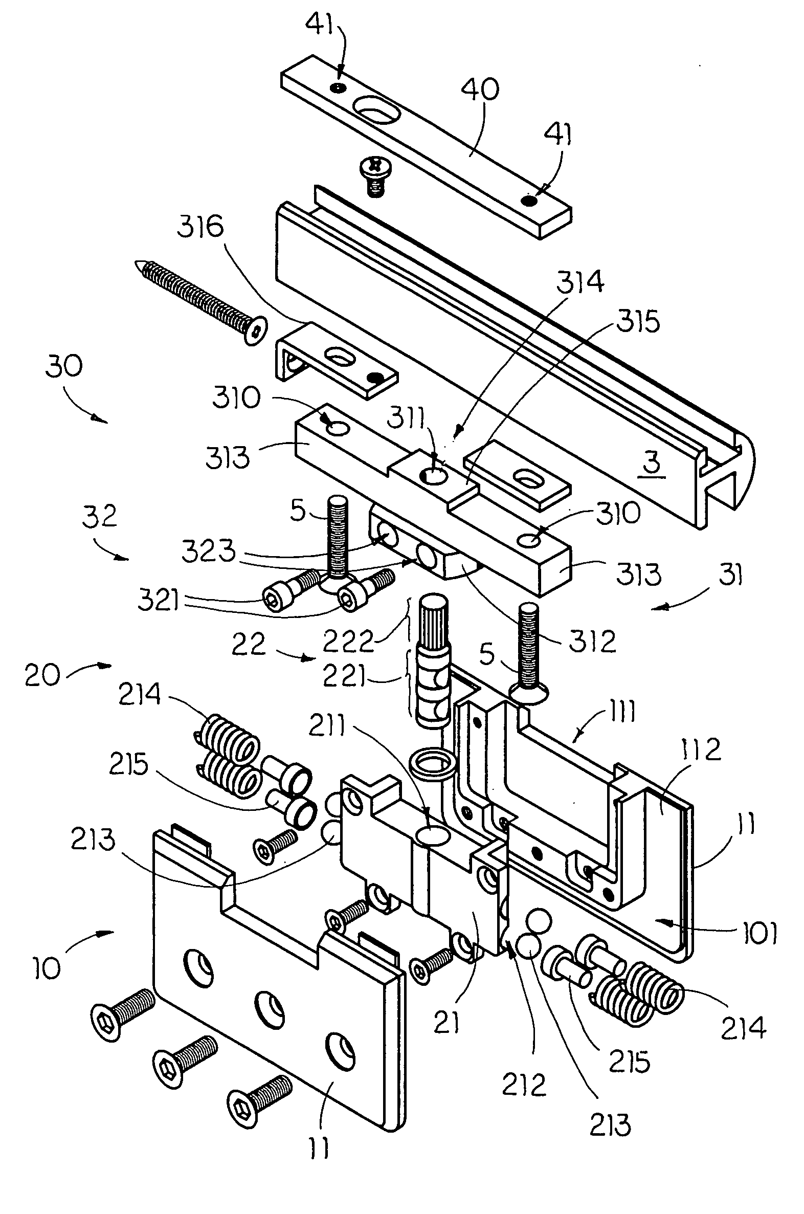
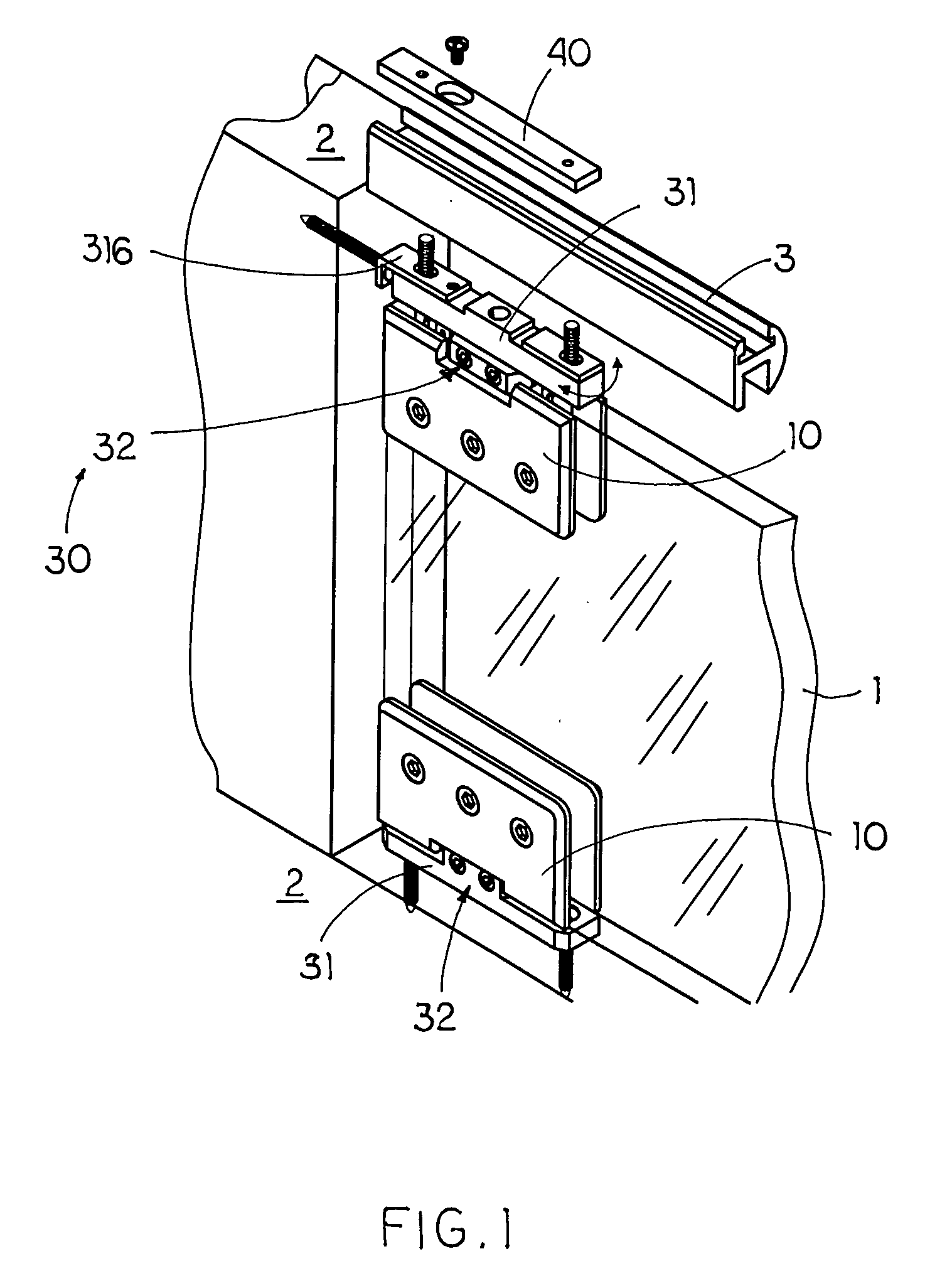
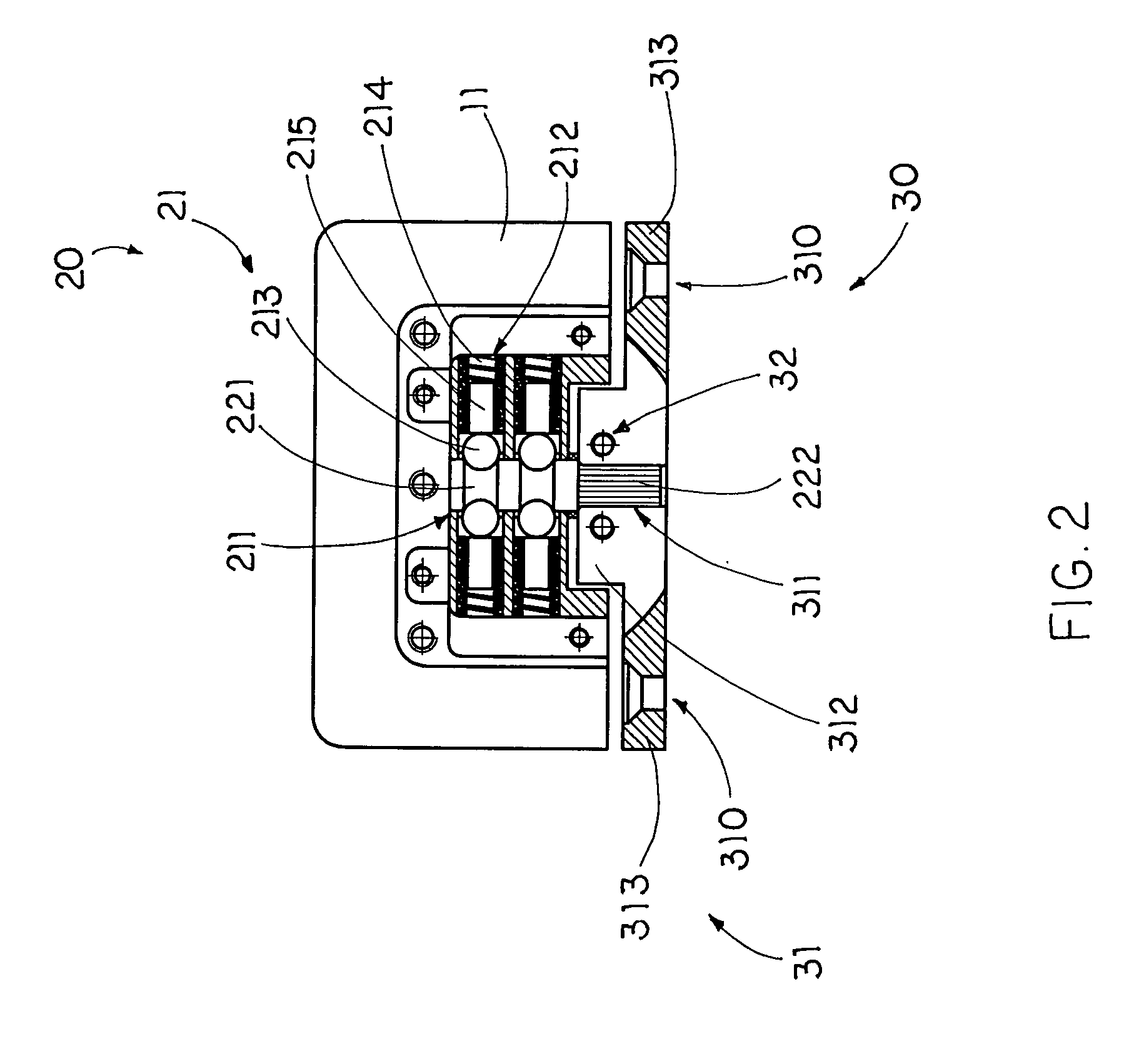
[0026]Referring to FIGS. 1 to 3 of the drawings, a pivot hinge for pivotally mounting a glass structure 1 to a border frame 2 according to a preferred embodiment of the present invention is illustrated, wherein the pivot hinge comprises a joint body 10, a joint hub 20 and an angular adjustment arrangement 30.

[0027]As shown in FIGS. 1 and 3, the glass structure 1 is embodied as a glass door pivotally mounted to a door frame as the border frame 2 via the pivot hinge of the present invention. It is worth to mention that the glass structure 1 can be a glass window pivotally mounted to a window frame as the border frame 2.

[0028]The joint body 10 comprises two spaced apart joint walls 11 defining a securing cavity 101 therebetween for securely sandwiching an edge portion of the glass structure 1 between the joint walls 11.

[0029]The joint hub 20 comprises a joint housing 21 securely mounted between the joint walls 11 within the securing cavity 101 and a supporting shaft 22 having a control...


PUM


Abstract

A pivot hinge for pivotally mounting a glass structure to a border frame, includes a joint body having two joint walls for securely sandwiching the glass structure, a joint hub including a supporting shaft having an adjusting portion, and an angular adjustment arrangement including a joint seat, having an adjustment sleeve, adapted for securely mounting to the border frame, wherein the adjusting portion of the supporting shaft is rotatably inserted into the adjustment sleeve in such a manner that the joint body is adapted to angularly move with respect to the joint seat for adjustably aligning the glass structure with the border frame and an angular adjustment locker securely lock up the supporting shaft within the adjustment sleeve in a rotatably movable manner for retaining an alignment of the glass structure in position with the border frame so as to pivotally mount the glass structure to the border frame.

Description

BACKGROUND OF THE PRESENT INVENTION[0001]1. Field of Invention[0002]The present invention relates to a pivot hinge assembly for a glass structure, and more particularly to a pivot hinge for a glass structure, which comprises an angular adjustment arrangement adapted to selectively adjust an angular position of the glass structure so as to finely align the glass structure with the border frame.[0003]2. Description of Related Arts[0004]A pivot hinge assembly normally used for pivotally mounting a glass door to a door frame, wherein the pivot hinge assembly comprises a top pivot hinge pivotally mounted at a top edge of the glass door to the door frame and a bottom pivot hinge pivotally mounted at a bottom edge of the glass door to the door frame. However, such pivot hinge assembly has several drawbacks.[0005]Each of the top and bottom pivot hinge generally comprises two cover walls to securely sandwich an edge portion of the glass door and a pivot joint rotatably mounted between the co...

Claims


Application Information

Patent Timeline
Patent Type & Authority Patents(United States)
IPC IPC(8): E05D11/00E05D11/10E05D5/02E05D5/00E05D7/08E05D5/10
CPCE05D5/0246E05D11/1064E05D5/10E05D11/1014E05D2011/1092Y10T16/554E05D7/081Y10T16/540257Y10T16/5323Y10T16/53238Y10T16/534E05Y2600/502
Inventor CHEN, MEI LI
Owner CHEN MEI LI
Why Eureka
Try Eureka