Foldable heat radiating sheet

a heat radiation board and foldable technology, applied in the direction of laminated elements, heating types, lighting and heating apparatuses, etc., can solve the problems of complicated installation, complicated manufacturing process, and buckling of fluid tubes, so as to facilitate installation at the installation site, reduce the number of construction elements, and facilitate the manufacturing process.

Inactive Publication Date: 2005-08-09
MITSUBISHI CHEM FUNCTIONAL PROD
View PDF28 Cites 24 Cited by
  • Summary
  • Abstract
  • Description
  • Claims
  • Application Information

AI Technical Summary

Benefits of technology

[0006]In view of the above-mentioned problems inherent in the prior art, the inventors of the present invention have conducted intensive studies and succeeded in completing the present invention. The present invention provides a heat radiation board, in which the number of construction elements (components) is reduced, the manufacturing process is not complicated, folding is possible, there hardly occur buckling of fluid tubes and damage due to friction with grooves formed in plate-like members at the time of packaging, storage, transportation, and installation, the installation at the installation site is facilitated, and a surface after the installation has a flat finish.

Problems solved by technology

With this conventional method, however, there occurs a problem that when the assembled wide heat radiation board is folded, the fluid tubes are buckled or are damaged by friction with the grooves provided in the plate-like members.
As a result of further studies conducted, however, there has been found that although the aforementioned problem can be solved, the heat radiation board having the proposed structure still suffers from problems in that the manufacturing process is complicated because the number of plate-like members is increased, the installation is also complicated because it is required to conduct the installation while fitting the fluid tubes in the grooves provided in the plate-like members, and the surface of the heat radiation board after the installation is uneven although a flat surface is desired.

Method used


Image

  • Foldable heat radiating sheet
  • Foldable heat radiating sheet
  • Foldable heat radiating sheet

Examples


embodiments

(Embodiments)

[0045]Specific embodiments of the present invention will now be described in detail with reference to the drawings. The following embodiments, however, should not be construed restrictively, and various modifications are possible without departing from the scope of the invention.

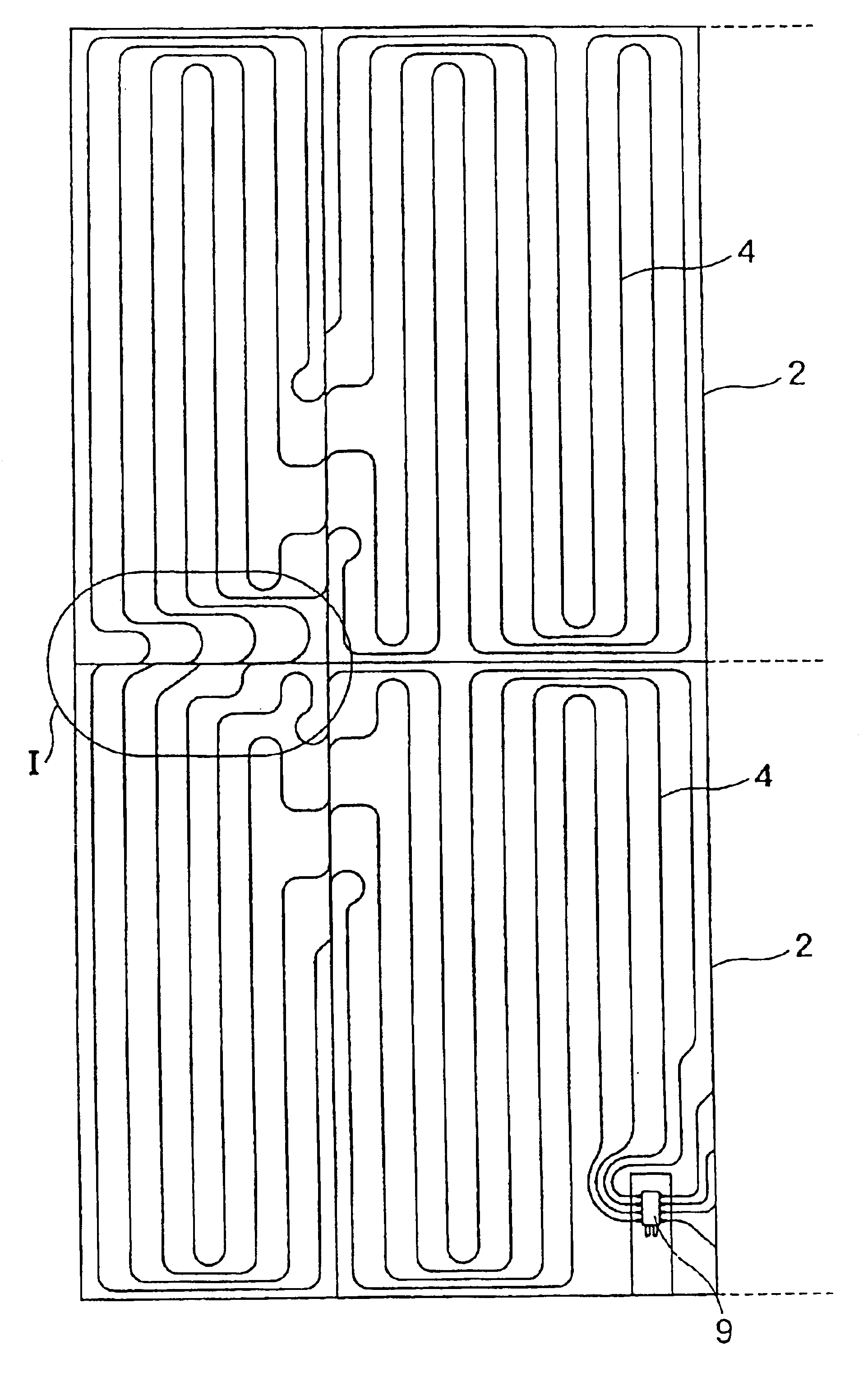
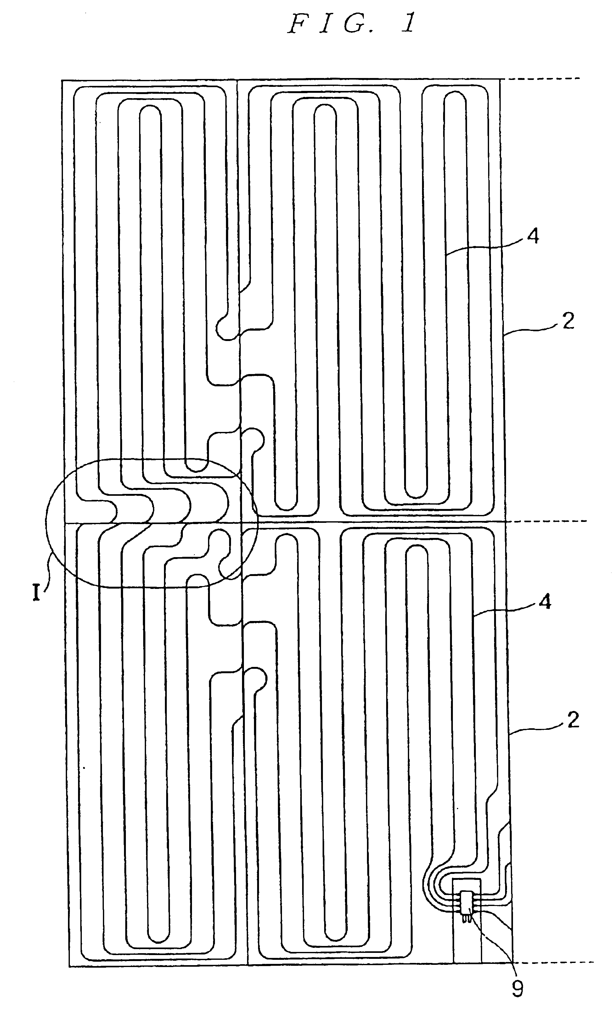
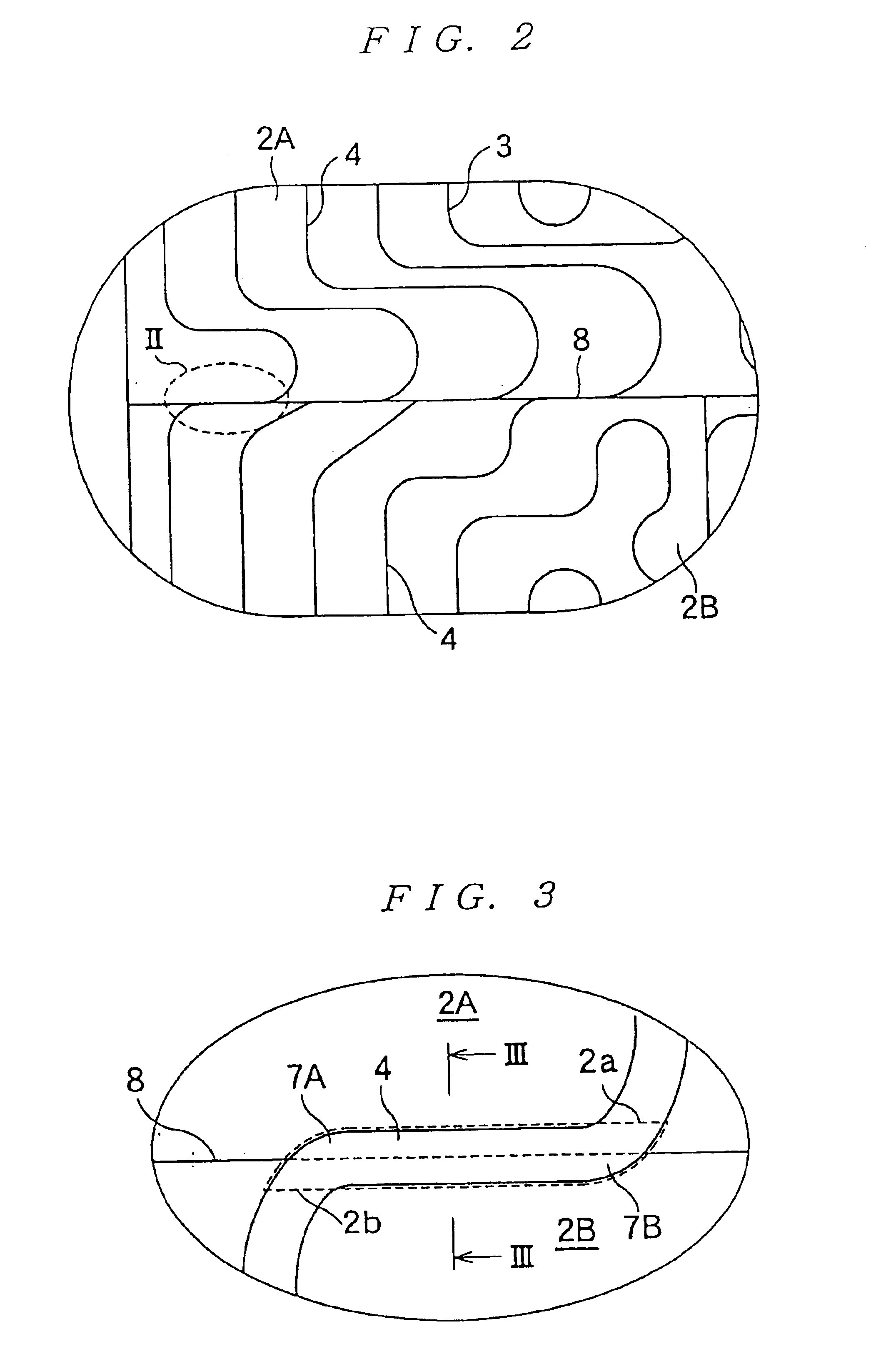
[0046]A heat radiation board 1 is formed to have an approximately quadrangular configuration by combining a plurality of elongated and narrow plate-like members 2 with each other. In FIG. 1, there is illustrated an example where four plate-like members 2 are combined with each other, although it is possible to increase the number of combined plate-like members to six, eight, or ten, for instance. Fluid tube embedding grooves 3 are provided on the front surface side of the plate-like members 2. In more detail, U-shaped grooves that change the extending directions of fluid tubes are provided in the end portions of the plate-like members 2, liner grooves that connect the U-shaped grooves in the end...


PUM


Abstract

A foldable heat radiation board includes a plurality of elongated and narrow plate-like members with fluid tube embedding grooves provided therein, and the plate-like members are combined with each other in a quadrangular plan configuration. Fluid tubes are embedded in the embedding grooves, and a heat radiation sheet is attached to the entire surface on the front surface side, while a back surface material is attached to the entire or partial surface on the back surface side. A plurality of contact portions in which the end portions of adjacent plate-like members contact each other are set as folding portions, and a fluid tube outlet opening portion in the end portion of one of the plate-like members and a fluid tube inlet opening portion in the end portion of the other of the plate-like members are provided so as not to oppose each other but to be shifted from each other, this portion being set as a fluid tube passage portion.

Description

TECHNICAL FIELD[0001]The present invention relates to a foldable heat radiation board, and in particular, to a foldable heat radiation board which is installed on the surface of a base material of a building, such as an ordinary housing, a condominium, a commercial building, or hotel. The heat radiation board is applicable to a wall surface, a ceiling board, a screen, or the like of a residential space, is capable of being folded, and is facilitated in packaging, storage, transportation, installation and other operations, whereby a flat-finished surface can be obtained after the completion of installation.BACKGROUND ART[0002]In order to achieve an improvement in the comfortability of houses in cold districts and the comfortability of houses in warm districts in the cold season, a floor heating technology for heating the inside of a house from the floor has conventionally been proposed and put into practical use. In the case of a detached house, there is adopted a technology with whi...

Claims


Application Information

Patent Timeline
Patent Type & Authority Patents(United States)
IPC IPC(8): F24D3/16F24D3/12
CPCF24D3/16Y02B30/00E04C2/52
Inventor KUGA, TAKESHIINOUE, MICHIAKIIIJIMA, SHIGEKO
Owner MITSUBISHI CHEM FUNCTIONAL PROD
Why Eureka
Try Eureka