Compensation and hoisting apparatus

a hoisting device and compensating technology, applied in the field of hoisting devices, can solve the problems of deformation of the drill collar, undue stress of the joint and possible failure, and the desire value of the hoisting bit to be maintained at the desired valu

Inactive Publication Date: 2005-08-09
ITREC BV
View PDF11 Cites 44 Cited by
  • Summary
  • Abstract
  • Description
  • Claims
  • Application Information

AI Technical Summary

Benefits of technology

[0011]It is furthermore an object of this invention to provide a simple c...

Problems solved by technology

In drilling a sub-aqueous well bore from a floating vessel, the heaving of the vessel under tide, wind and wave conditions introduces problems of maintaining the drilling weight on the bit at the desired value.
In addition, the vertical movement of the drill string causes the shifting of stresses in the drill collars where the point of neutral stress (change between compression and tension) may cross a drill collar or pipe joint causing undue stressing of such joint and possible failure.
Such constantly changing stress at drill collar sections may cause deformation of the drill collars and produce unnecessary cutting of sides of a hole or hole deviation by the resultant dissipation of drilling energy into a lateral direction instead of a vertical direction.
The traveling compensator system works but adds to the ton miles of work done by the draw works.
The draw works is mounted on and moving with the heaving vessel and complicates the situation.
The greatest drawback, however, is the added structural mass high in the derrick.
The technical burden of the currently available compensator systems is constant whether they are active or passive, in terms of the dead weight present far above the vessel metacentric height.
Also one of the main disadvantages of compensating devices where the drill string is supported hydraulically is the vessel motion dependent behavior of the hydraulic spring that is supporting the load.
This makes the system unsuitable to compens...

Method used


Image

  • Compensation and hoisting apparatus
  • Compensation and hoisting apparatus
  • Compensation and hoisting apparatus

Examples


second embodiment

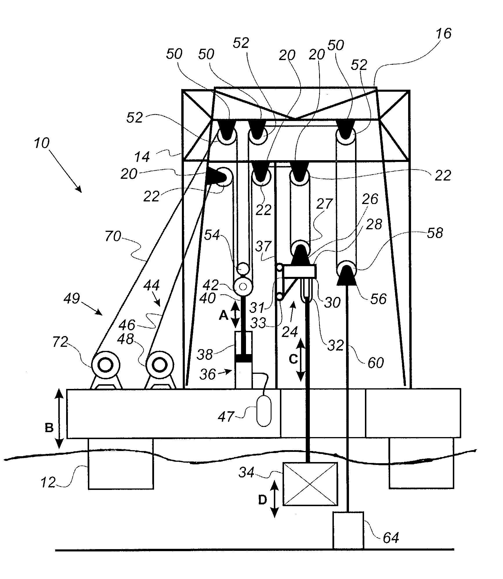
[0049]FIG. 3 shows the invention. As can be seen, the connection cable (60) to the fixed reference (64) is no longer present. Instead a motion and load sensing device (82) is used to measure the tension in the hoisting cable (46) and the movement of the vessel (12).

[0050]The secondary hoisting mechanism (72) is controlled in such a way that it counteracts any movements of the vessel (12) and any unwanted tension variations of the compensator (36). Since the secondary compensator (49) is smaller than the compensator (36) the power that is needed to compensate for tension variations is also smaller. When this ratio is 0.9 the power that is needed for the second compensation system (49) is approximately 10% of the total compensation power. The remaining 90% is provided by the compensator (36). This compensator system is often a passive system which comprises an energy storage to reduce the overall power demand of the system to almost zero. The advantage of this embodiment is that the s...

third embodiment

[0051]FIG. 4 shows the hoisting device (10). This embodiment does not use a secondary hoisting mechanism (72) to compensate for the movement of the vessel or tension variations of the compensator (36) but instead uses a third compensator (80) having a first end (86) and a second end (88), which is at the second end (88) connected to pulleys (42). The compensator second end (88) is movable with respect to the first end (86) and compensator (80) is mounted on the vessel (12). A motion and load sensing device (82) is visible to detect the tension in hoisting cable (46) and / or the movement of the vessel (12) which is connected to a controller (90) to control compensator (36) by mechanism of third compensator (80).

[0052]FIG. 5 show's the hoisting device (10) in which are at least two winches, (48, 51) each end of the hoisting cable (46) being wound into a separate winch (48, 51). The winches (48, 51) are driven by a plurality of motors with low inertia. Also in this embodiment each end o...


PUM


Abstract

The invention is a hoisting device for a vessel a base structure provided with fixed cable blocks with pulleys; a trolley connected to a cable pulley block and a mechanism for gripping a load; a compensator a hoisting mechanism with a hoisting cable and a winch, wherein the hoisting cable is guided over the cable pulleys connected to the base structure and is adapted to move the trolley relative to the base structure with the aid of the winch; a secondary compensator with fixed cable blocks and pulleys connected to the base; a cable pulley set connected to the compensator end; a connection cable connected to a stationary section and a movable cable block with pulleys; a hoist connected to the vessel; a connecting cable guided over pulleys; and movable cable block and is adapted to move the compensator second end with the aid of the secondary hoisting mechanism.

Description

[0001]The present continuation in part application claims priority to patent application Ser. No. 09 / 807,078 now U.S. Pat. No. 6,595,494 filed in the U.S. Patent and Trademark Office on Jul. 2, 2001.FIELD OF THE INVENTION[0002]The present invention relates to a hoist system connected to a floating vessel that minimizes the energy consumption and operating cost of lifting operations.BACKGROUND OF THE INVENTION[0003]The present invention relates to apparatus for controlling the stress in a running string, and more particularly to apparatus used on or in connection with a floating vessel for maintaining the strain in a running string, such as a pipe string, substantially constant while being used in the performance of diverse functions in a sub-aqueous well bore, such as drilling and completion operations therein, despite vertical movement of the vessel while such operations are being performed.[0004]In the normal operation of drilling a well bore on land, or from a drilling platform s...

Claims


Application Information

Patent Timeline
IPC IPC(8): E21B19/00E21B19/09B66D3/04
CPCB66D3/043B66D3/046E21B19/008E21B19/09Y10S254/90
Inventor DE GROOT, ANNE KLAASROODENBURG, JOOPVAN KUILENBURG, ROBERT FRODO
Owner ITREC BV
Why Eureka
Try Eureka