Quick coupler for removably joining two pipes

a technology of removable jointing and quick coupler, which is applied in the direction of hose connection, pipe-joint, coupling, etc., and can solve problems such as user injury

Inactive Publication Date: 2005-08-09
STAUBLI FAVERGES SA
View PDF7 Cites 17 Cited by
  • Summary
  • Abstract
  • Description
  • Claims
  • Application Information

AI Technical Summary

Benefits of technology

[0019]An intermediate piece adapted to receive the body of the male element and provided with means for locking this body is provided in the female element, the afore-mentioned locking means being adapted to release the body of the male element when the latch is displaced under the effect of the afore-mentioned elastic means. This intermediate piece is advantageously loaded towards a position where the afore-mentioned locking means are not active.

Problems solved by technology

A device is thus produced whose functioning is secured and which does not allow uncoupling, accidental or otherwise, of the male and female elements when the coupler is under pressure, whereby a user might be injured.

Method used


Image

  • Quick coupler for removably joining two pipes
  • Quick coupler for removably joining two pipes
  • Quick coupler for removably joining two pipes

Examples


Embodiment Construction

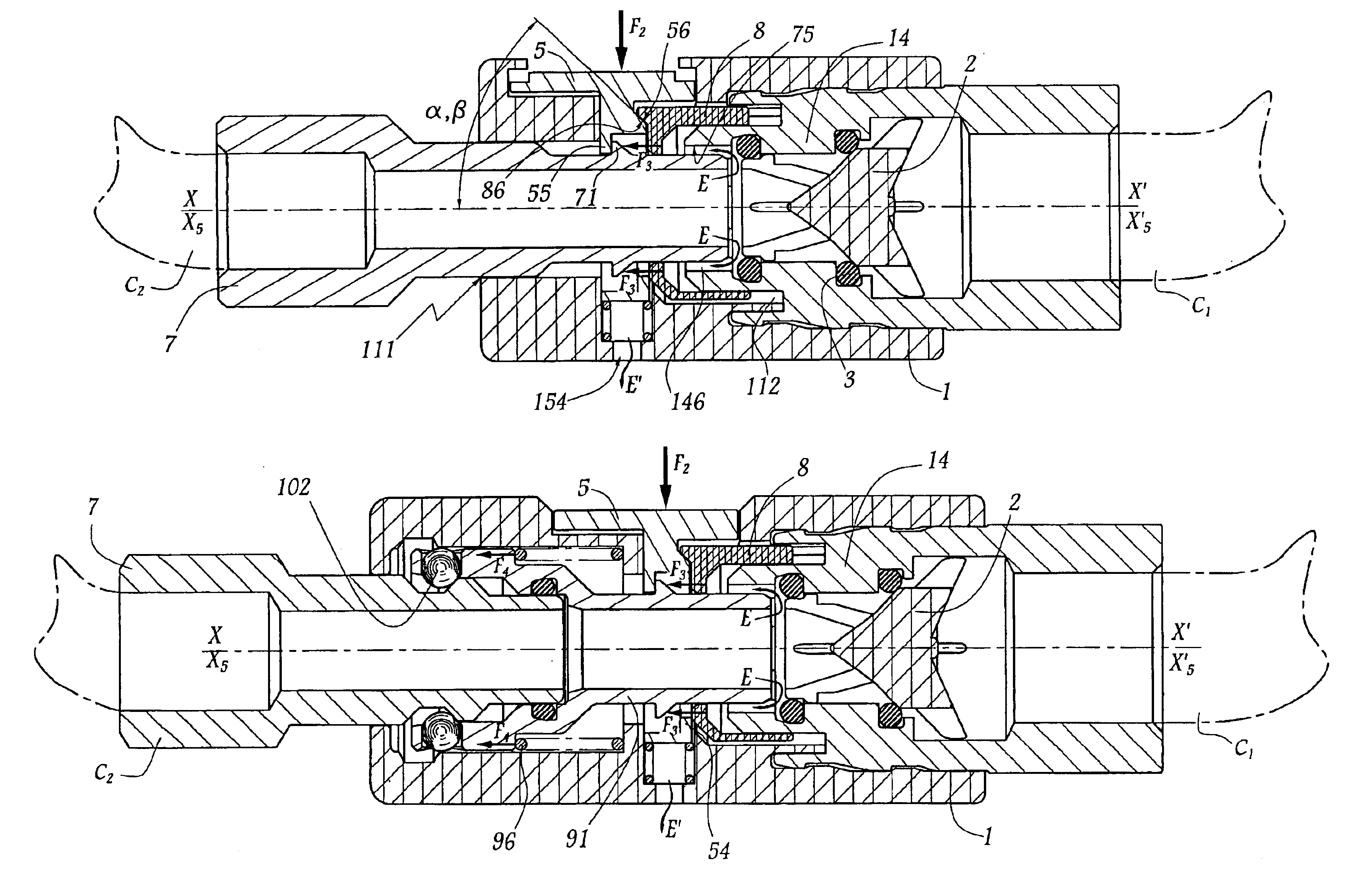
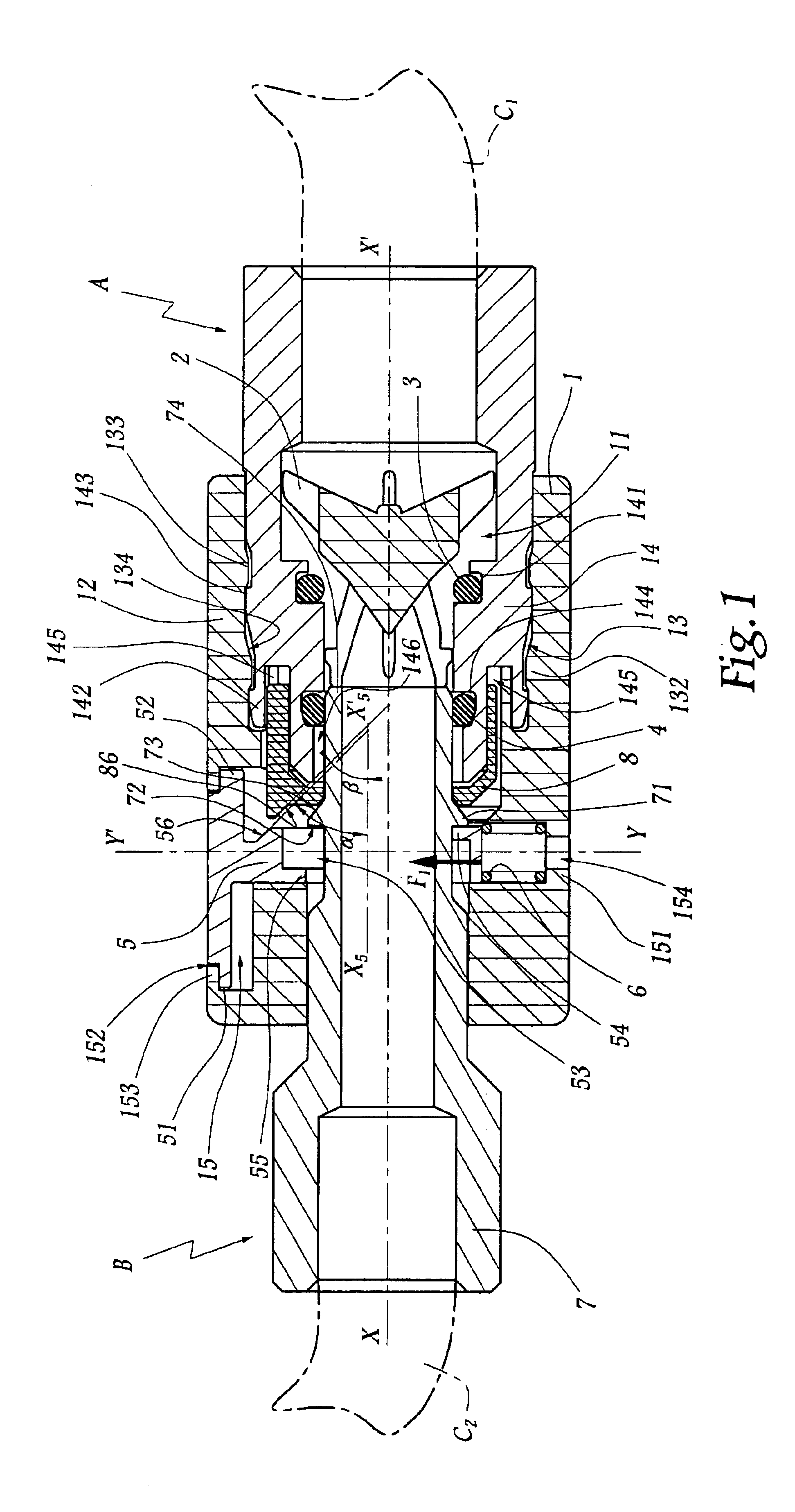
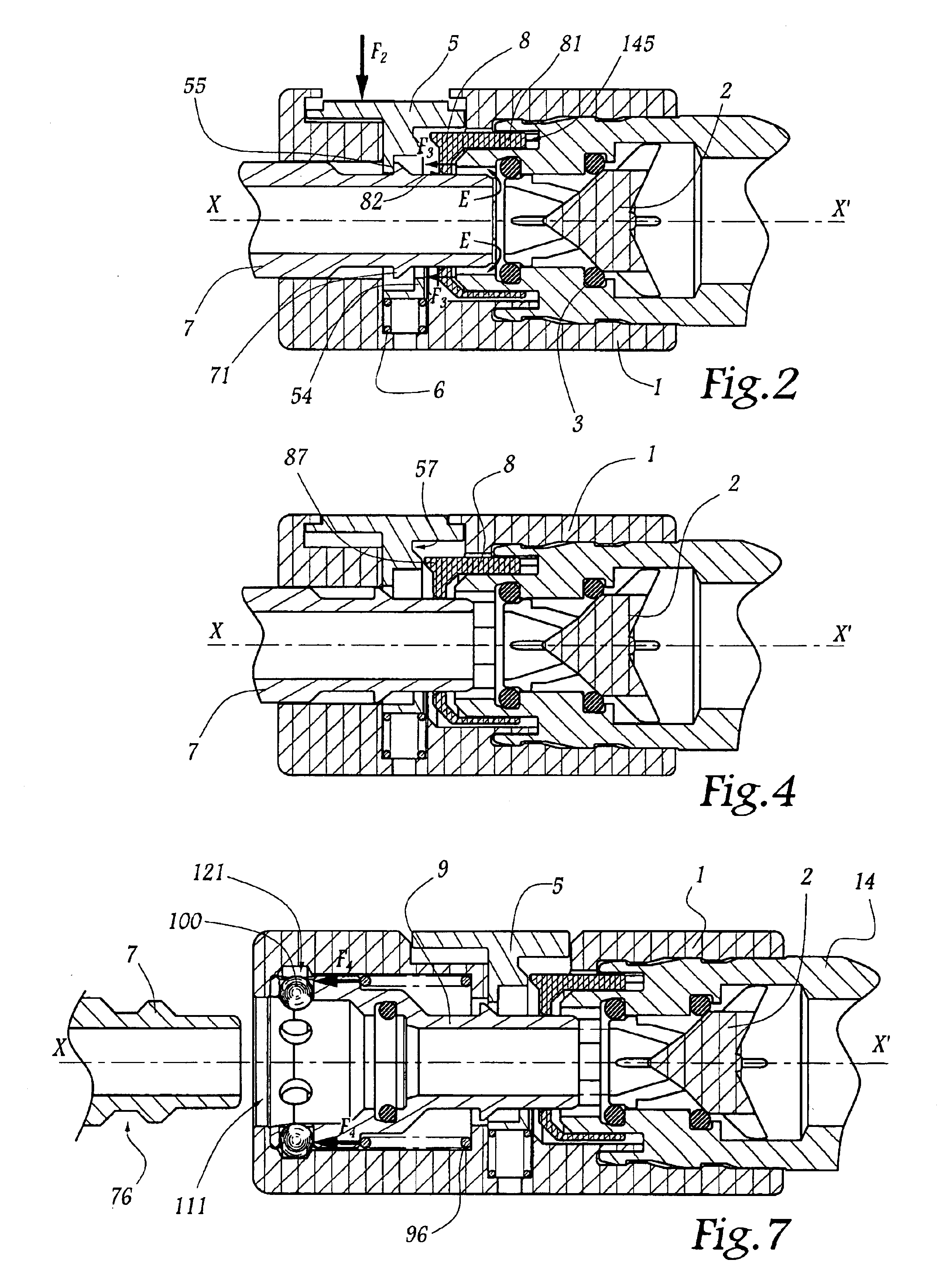
[0028]Referring now to the drawings, the coupler shown in FIGS. 1 to 4 comprises a female element A and a male element or connector B connected respectively to an upstream pipe C1 and to a downstream pipe C2. The upstream pipe C1 is itself connected to a source of fluid under pressure (not shown).

[0029]The outside shape of the body 1 of the female element is substantially cylindrical and circular, centred on an axis X-X′ which is also the longitudinal axis of a conduit 11 inside the body 1 and in which is arranged a valve 2 mobile along axis X-X′. The body 1 is in two parts and comprises a principal part 12 forming a bore 13 in which is immobilized a secondary part 14 fast with the pipe C1. In practice, the valve 2 is mounted in part 14 which defines a groove 141 for receiving an O-ring 3 for seal of the valve 2.

[0030]The outer radial surface of part 14 is provided with catches 142 and 143 intended to cooperate with catches 132 and 133 provided on the inner radial surface 134 of the...


PUM


Abstract

A quick coupler for joining two pipes that includes a male element adapted to be fitted into a female element and maintained in position by a latch forming a stop and opposing withdrawal of the male element. A movable safety member maintains the latch in a blocked position, under the force of pressure of fluid in the coupler, by the cooperation of two surfaces provided, one on the latch and one on the safety member, that are forced into engagement with one another. The safety member releases the latch when a residual pressure in the coupler drops to a safe level.

Description

BACKGROUND OF THE INVENTION[0001]1. Field of the Invention[0002]The present invention relates to a quick coupler for the removable join of pipes conveying fluid under pressure.[0003]2. Brief Description of the Related Art[0004]Patent FR-2 514 855 discloses a quick coupler which comprises two elements, male and female, adapted to fit axially, provoking the opening of a closure valve mounted in the body of the female element, this body being equipped with a loaded latch or button, mounted to slide in this body and pierced with a central opening for fit of the male element. The wall of the opening of the latch presents teeth offset with respect to one another along a median axis of this opening, while the male element is provided with a shoulder adapted to rest selectively against one or the other of these teeth. When the coupler is in configuration for passage of fluid, a first tooth of the latch maintains the male element in place in the female element. When the coupler is unlocked, ...

Claims


Application Information

Patent Timeline
Patent Type & Authority Patents(United States)
IPC IPC(8): F16L37/00F16L37/084F16L37/23F16L37/38
CPCF16L37/0841F16L37/23Y10S285/924F16L37/40
Inventor LACROIX, JEAN-JACQUESPASTORE, OLIVIER
Owner STAUBLI FAVERGES SA
Why Eureka
Try Eureka