
Attachment for blade of hockey stick

a technology of hockey stick and blade, which is applied in the field of attachment of hockey stick blade, can solve the problems of insufficient length of the apparatus, undesirable refuse, and inconvenient installation of the equipment, so as to minimize any change in the balance of the playing stick and the cost of manufactur

Inactive Publication Date: 2005-08-09
DEHEN MARTIN L
View PDF30 Cites 11 Cited by
  • Summary
  • Abstract
  • Description
  • Claims
  • Application Information

AI Technical Summary

Benefits of technology

[0021]An advantage of the present invention is that yard waste can be removed to a remote location without touching the yard waste, without bending down, and without smelling the yard waste at a close range.
[0022]Another advantage of the present invention is that yard waste can be removed to a remote location with great accuracy and over a great distance.
[0023]Another advantage of the present invention is that the present attachment, with no changes, may slide onto either a right-handed or left-handed playing stick.
[0024]Another advantage of the present invention is that the present attachment is inexpensive to manufacture.
[0025]Another advantage of the present invention is that the present attachment is relatively lightweight to minimize any change in the balance of the playing stick.
[0026]Another advantage of the present invention is that the attachment may be utilized on a number of playing sticks, including hockey sticks, lacrosse sticks, bandy sticks, and field hockey sticks.

Problems solved by technology

Yard waste often includes undesirable refuse such as rotten hornet-infested crab apples and dog waste.
Such refuse is undesirable for a number of reasons, including the consistency of the refuse such as its relative hardness or softness and the odor given off by the refuse.
If the waste is being picked up by an apparatus, the apparatus may not have features permitting one to fling the waste to a desired spot such as a compost heap, and the apparatus may not have a sufficient length permitting a spacing of one from the waste.
If the waste is being picked up by hand, one must bend down relatively close to the waste that may have an undesirable smell.
If the waste is to be flung by hand to a desired location such as a compost heap, the waste may crumble upon the head of one who throws the waste.

Method used


Image

  • Attachment for blade of hockey stick
  • Attachment for blade of hockey stick
  • Attachment for blade of hockey stick

Examples


Embodiment Construction

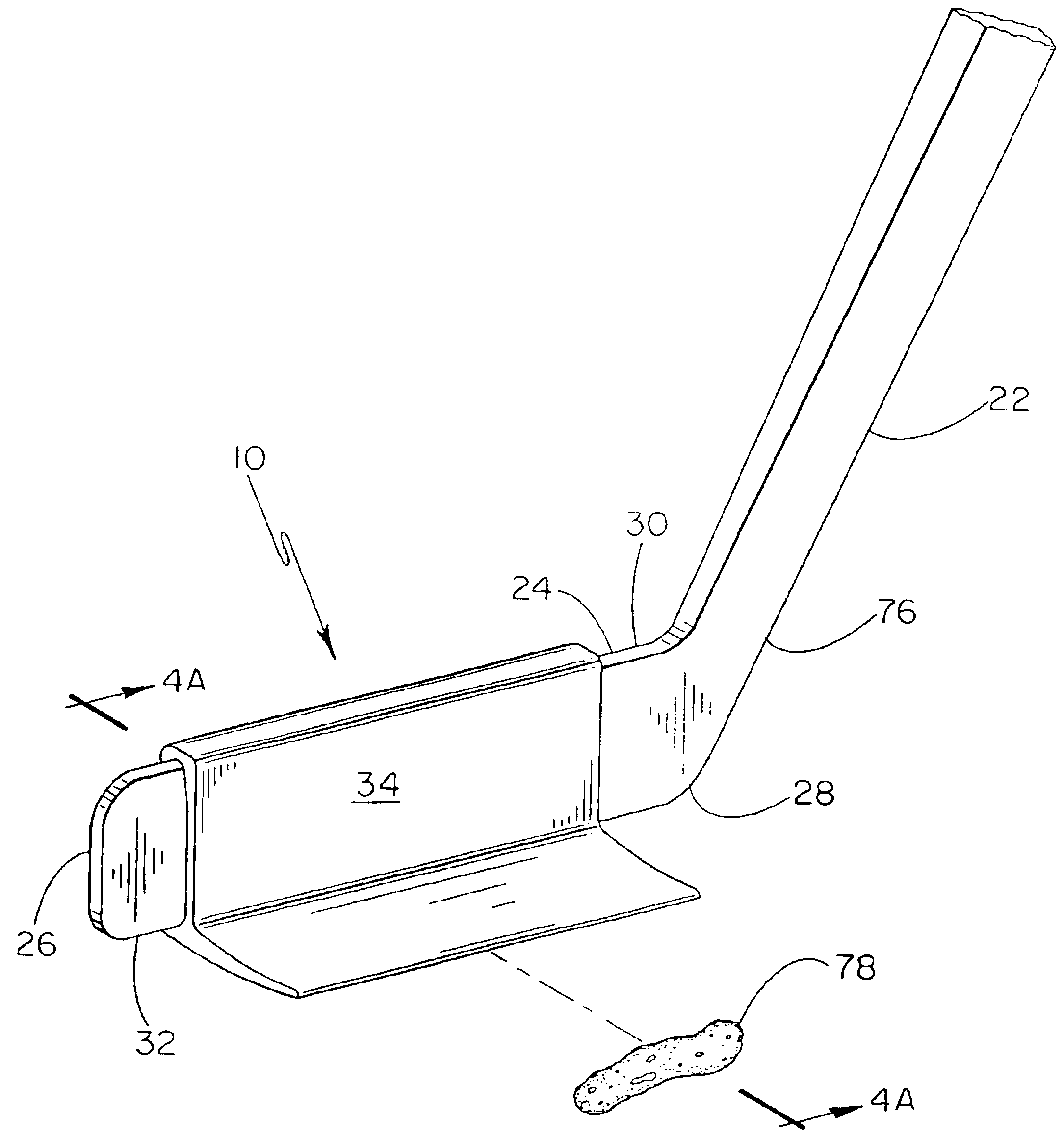
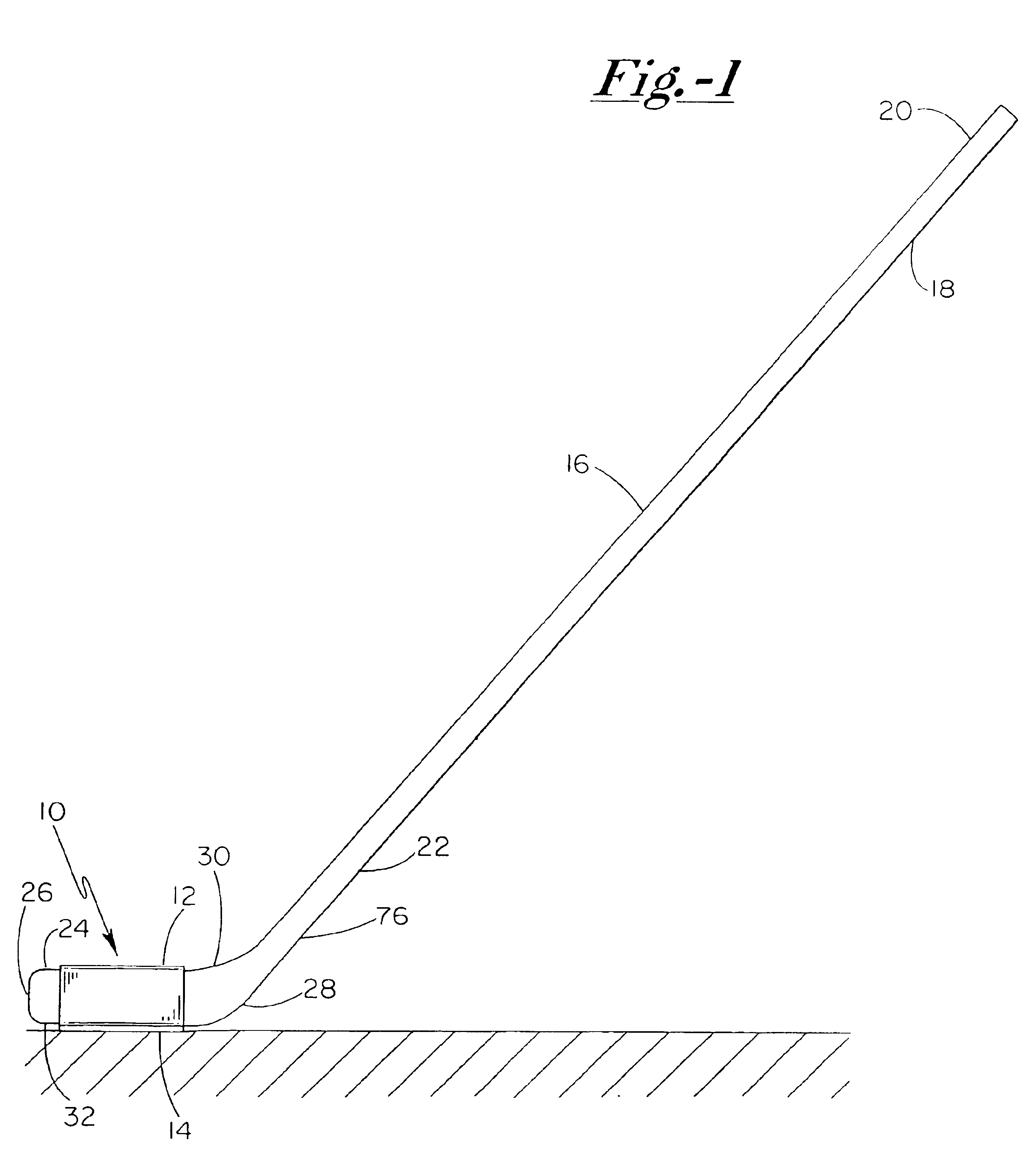
[0045]As shown in FIG. 1, the present invention is indicated in general by reference number 10. Attachment 10 includes a base portion 12 and a floor portion 14. Attachment 10 is engaged to a hockey stick 16. Hockey stick 16 includes a proximal end portion 18 that includes a handle 20. Hockey stick 16 further includes a distal end portion 22 that includes a blade 24. Blade 24 includes a toe end 26 and a heel end 28. Blade 24 further includes an upper edge 30 and a lower edge 32.

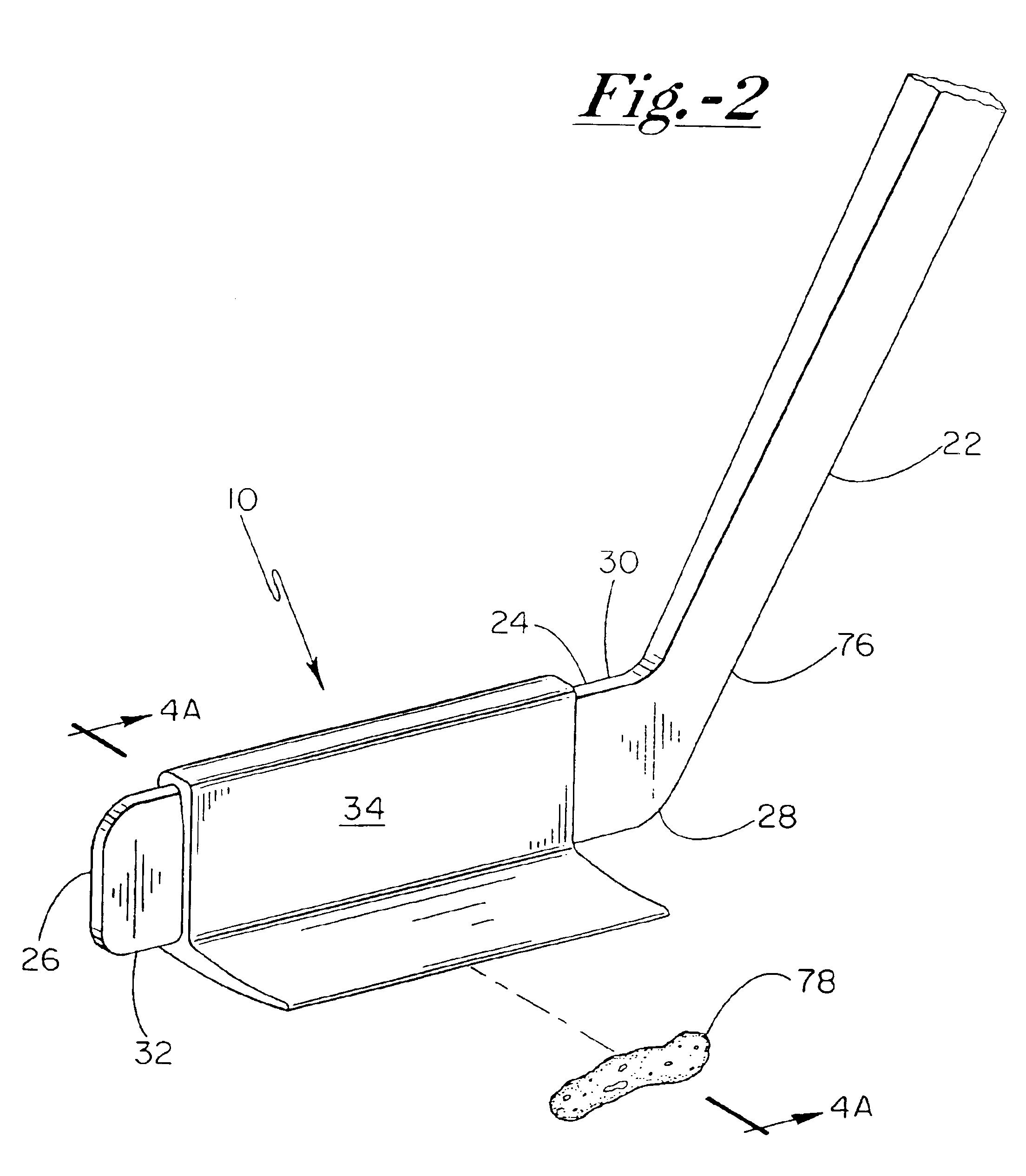
[0046]As shown in FIGS. 2, 3A and 3B, base portion 12 includes a first or front face 34, a second or rear face 36 that opposes the front face 34 and runs generally parallel to the front face 34. Front face 34 and rear face 36 define a blade section 38 of base portion 12. Blade section 38 runs generally parallel to the blade 24 of the hockey stick 16 when the attachment 10 is on the blade 24.

[0047]Base portion 12 further includes an upper grip 40 for engaging the upper edge 30 of the blade 24. The upper grip 40...


PUM


Abstract

An attachment for a blade of a playing stick such as a hockey stick. The attachment includes a floor portion with a leading edge that digs under an object to be flung by the stick. The attachment includes a base portion that engages the blade. The floor portion may be flexed between an L-shaped position and a V-shaped position, relative to the base portion or blade. The attachment may include a finger for engaging the heel end of the blade, ceiling portion, a seat on the floor portion, an undulating leading edge, a slot for being engaged by a tether that wraps about the blade, and a base portion that is curved for a curved blade. An attachment having the blade itself is further disclosed, where a heel end of the attachment engages the blunt distal end of a stick.

Description

[0001]This application claims the benefit under 35 U.S.C. 119(e) of U.S. Provisional Patent Application No. 60 / 423,436 filed Nov. 4, 2002.FIELD OF THE INVENTION[0002]The present invention relates generally to an attachment for a blade of a playing stick, particularly to an attachment for a blade of a hockey stick, and specifically to a blade of a hockey stick having a floor portion.BACKGROUND OF THE INVENTION[0003]A hockey stick is a structure that can hit an object, such as a hockey puck, with great force, with great control, and over a relatively great distance. For example, when hit by a hockey stick, a hockey puck can fly from one end to another end of a hockey rink at 100 mph or more precisely into a desired corner of the net.[0004]Yard waste often includes undesirable refuse such as rotten hornet-infested crab apples and dog waste. Such refuse is undesirable for a number of reasons, including the consistency of the refuse such as its relative hardness or softness and the odor ...

Claims


Application Information

Patent Timeline
Patent Type & Authority Patents(United States)
IPC IPC(8): E01H1/00E01H1/12A63B59/12A63B59/02A63B59/00
CPCA47L13/00A63B47/02A63B59/14E01H1/12A63B59/02A63B59/12A63B2059/0007A63B2208/12A63B2243/005E01H2001/1293A63B2102/24A63B59/70A63B2102/14A63B59/20A63B2102/22A63B60/004
Inventor DEHEN, MARTIN L.
Owner DEHEN MARTIN L
Learn More