Electret acoustic transducer array for computerized ultrasound risk evaluation system

a technology of computerized ultrasound and acoustic transducers, applied in the field of acoustic imaging systems, can solve the problems of significant limitations of conventional ultrasound, relatively expensive procedures, and inability to provide information on the properties of materials in ultrasonic b scans

Inactive Publication Date: 2005-08-09
BARBARA ANN KARMANOS CANCER INST
View PDF96 Cites 57 Cited by
  • Summary
  • Abstract
  • Description
  • Claims
  • Application Information

AI Technical Summary

Problems solved by technology

There are a number of disadvantages associated with various imaging systems that are currently in use, particularly when used for medical applications.
Also, CT scans and magnetic resonance imaging (MRI) techniques both involve procedures that are relatively expensive, a factor that by itself acts to some degree to limit their use.
A significant disadvantage of methods such as mammography is that they rely on two-dimensional images that may disguise three-dimensional structure information that can be critical for diagnosis.
There are, however, significant limitations to conventional ultrasound, which may be used in A or B scanning modes.
This arrangement results in two major drawbacks.
First, ultrasonic B scans do not provide information on the properties of the materials themselves; rather, they provide information only on the reflectivity of the boundaries between different types of materials.
Second, the array is incapable of capturing radiation except that reflected back to the hand-held sensing array.
Factors that inhibit the development of such systems include limitations on the cost of appropriate acoustic transducers, such costs being influenced by needs for high sensitivity and small size.

Method used


Image

  • Electret acoustic transducer array for computerized ultrasound risk evaluation system
  • Electret acoustic transducer array for computerized ultrasound risk evaluation system
  • Electret acoustic transducer array for computerized ultrasound risk evaluation system

Examples


Embodiment Construction

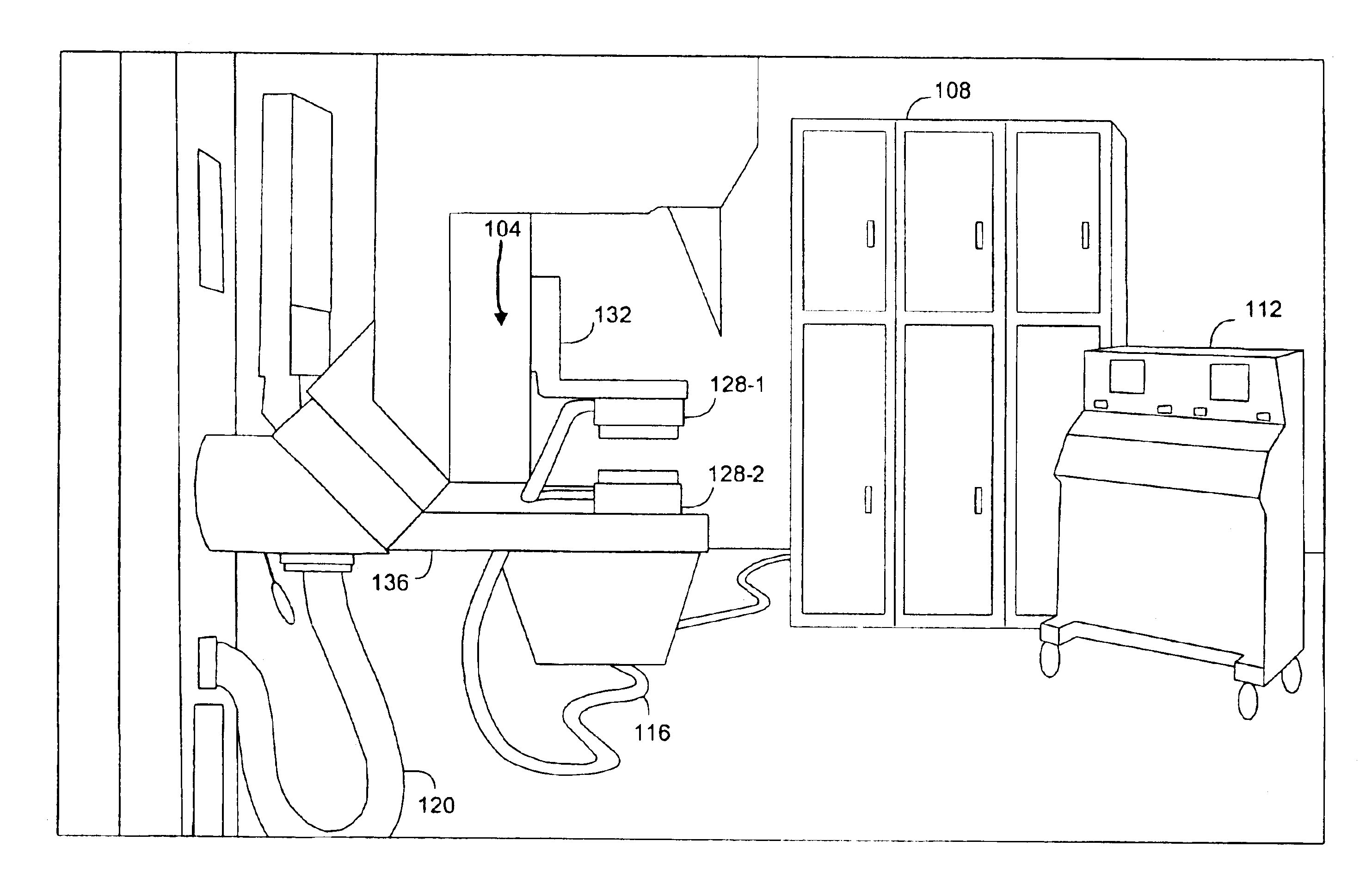
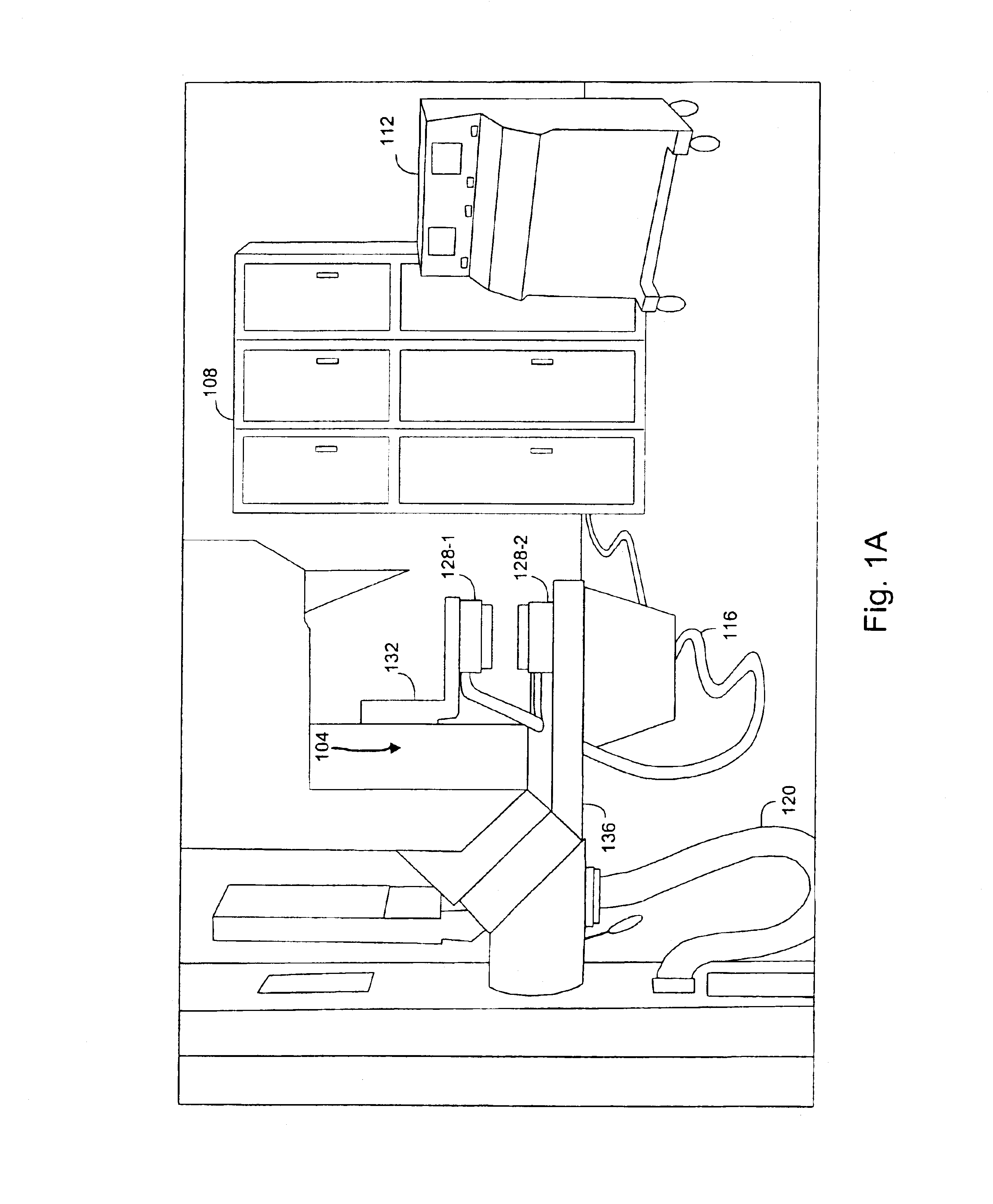
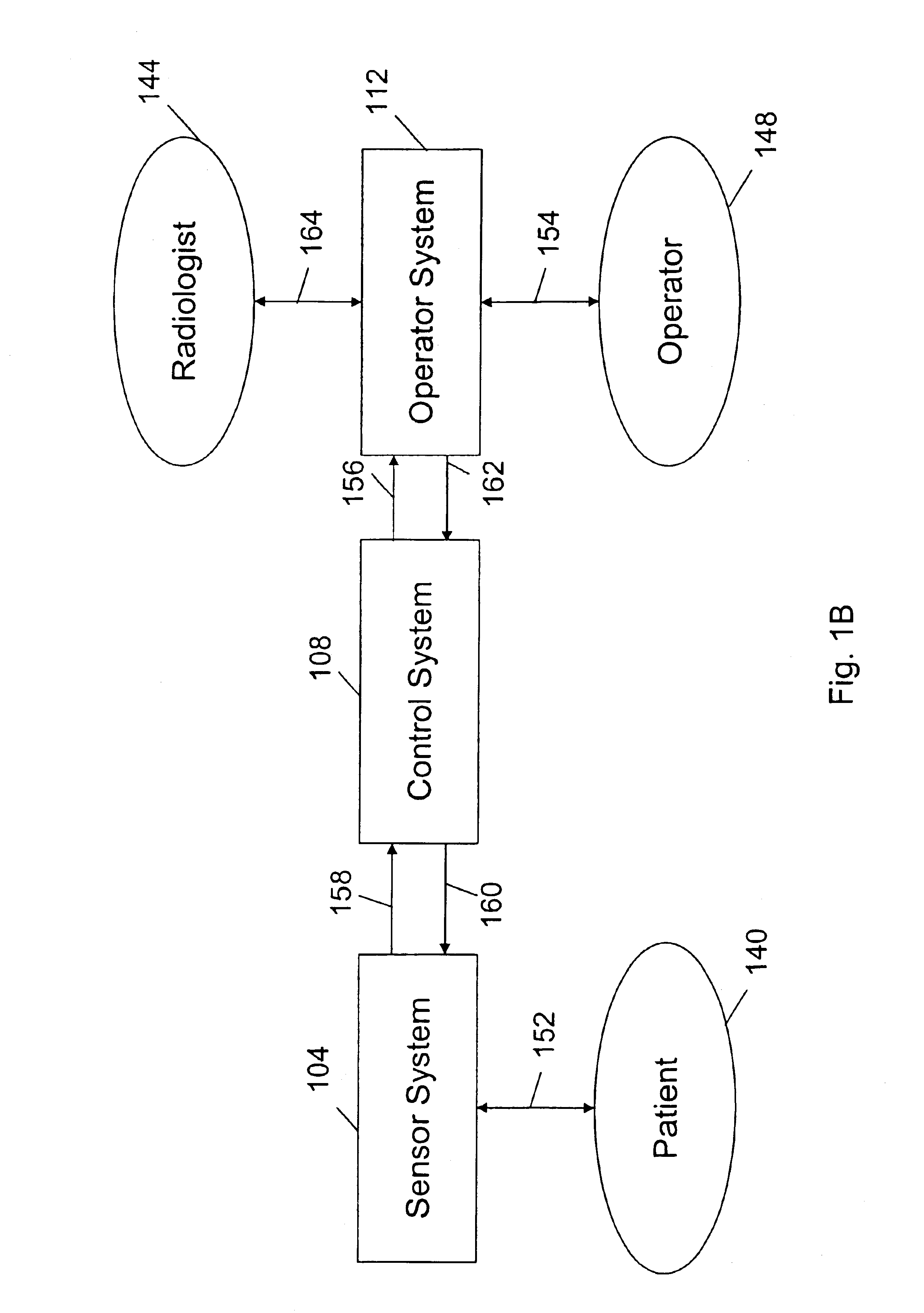
[0015]Embodiments of the invention are directed generally to acoustic transducer arrays that may be used in systems for examining objects under study, such as tissue. FIGS. 1A and 1B provide a general structural overview of such a system that may be configured according to an embodiment of the invention appropriate for medical applications, particularly for ultrasound imaging of a patient's breast. Additional aspects of such a system are described the following commonly assigned patents and patent applications, the entire disclosures of all of which are herein incorporated by reference for all purposes: U.S. Pat. No. 6,385,474 entitled “METHOD AND APPARATUS FOR HIGH-RESOLUTION DETECTION AND CHARACTERIZATION OF MEDICAL PATHOLOGIES,” filed March 19, 1999 by John D. Rather et al., which is a nonprovisional of U.S. Prov. Pat. Appl. No. 60 / 078,788 entitled “HIGH RESOLUTION ULTRASOUND ANATOMICAL IMAGING SYSTEM,” filed Mar. 20, 1998 by John D Rather; U.S. Pat. Appl. No. 10 / 323,354, entitle...


PUM


Abstract

An electret-based acoustic transducer array is provided and may be used in a system for examining tissue. The acoustic transducer array is formed with a substrate that has a multiple distinct cells formed therein. Within each of the distinct cells is positioned an acoustic transducing element formed of an electret material. A conductive membrane is formed over the distinct cells and may be flexible.

Description

STATEMENT AS TO RIGHTS TO INVENTIONS MADE UNDER FEDERALLY SPONSORED RESEARCH OR DEVELOPMENT[0001]The Government has rights in this invention pursuant to U.S. Dept. of Energy Work for Others Agreement L-8420.BACKGROUND OF THE INVENTION[0002]The present invention relates generally to acoustic imaging systems. More particularly, the present invention relates to acoustic transducers for use in acoustic imaging systems.[0003]There are a number of disadvantages associated with various imaging systems that are currently in use, particularly when used for medical applications. For example, a number of imaging techniques, such as x-ray imaging, mammography, and computed tomographic (CT) scans, use ionizing radiation that presents a risk of cell mutation when used medically. Also, CT scans and magnetic resonance imaging (MRI) techniques both involve procedures that are relatively expensive, a factor that by itself acts to some degree to limit their use. A significant disadvantage of methods s...

Claims


Application Information

Patent Timeline
Patent Type & Authority Patents(United States)
IPC IPC(8): A61B8/14B06B1/02
CPCA61B8/14B06B1/0292
Inventor MOORE, THOMAS L.FISHER, KARL A.
Owner BARBARA ANN KARMANOS CANCER INST
Why Eureka
Try Eureka