Spinal fusion apparatus and method

a technology of spinal cord and fusion tube, which is applied in the field of spinal cord fusion tube and method, can solve the problems of more difficult unintentional disturbance of implants, and achieve the effects of restoring strength to the spinal column, reducing nerve pressure, and facilitating fusion

Inactive Publication Date: 2005-08-09
WARSAW ORTHOPEDIC INC
View PDF25 Cites 161 Cited by
  • Summary
  • Abstract
  • Description
  • Claims
  • Application Information

AI Technical Summary

Benefits of technology

[0014]Therefore, the objects of the present invention are: to provide a spinal stabilizing system having an apparatus including implants that are positioned in bores between vertebrae having a degenerated or damaged disc wherein the implants include live bone or are constructed of bone growth enhancing material for generating fusion between the vertebrae and wherein the implants are joined for greater stabilization during the fusion process; to provide such an apparatus that provides for proper spacing and alignment between the vertebrae thereby relieving pressure on nerves, restoring strength to the spinal column and correcting other problems associated with vertebrae misaligned due to disc failure or related damage; to provide such an apparatus including structure to further join implants to adjacent vertebrae above and below the implants and other implants so as to additionally improve stabilization of the implant during the fusion process; to provide anterior end caps for each cage that support the anterior endplate of vertebrae spaced by the cages, so as to resist subsidence of the vertebrae onto the cages and to resist rotation of the cages; to provide such an apparatus wherein the implants are joined in such a manner that the axes thereof are nonparallel so as to substantially reduc

Problems solved by technology

This urges and preloads the implants into the sidewalls of the implant receiving bores, which may also be non-parallel, and makes it m

Method used


Image

  • Spinal fusion apparatus and method
  • Spinal fusion apparatus and method
  • Spinal fusion apparatus and method

Examples


first embodiment

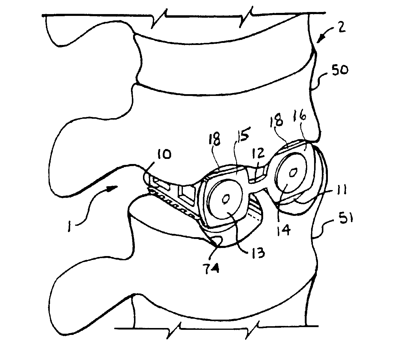
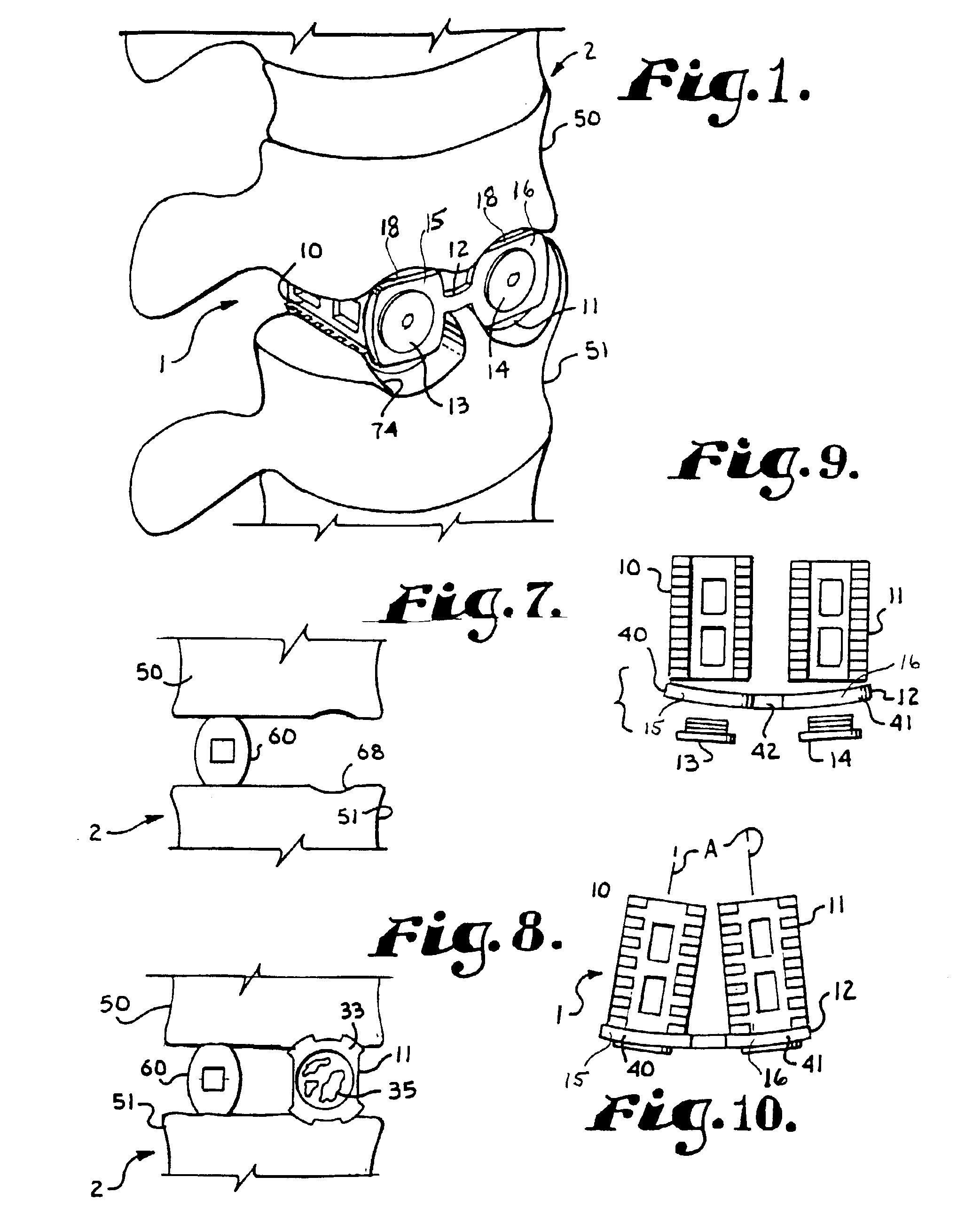
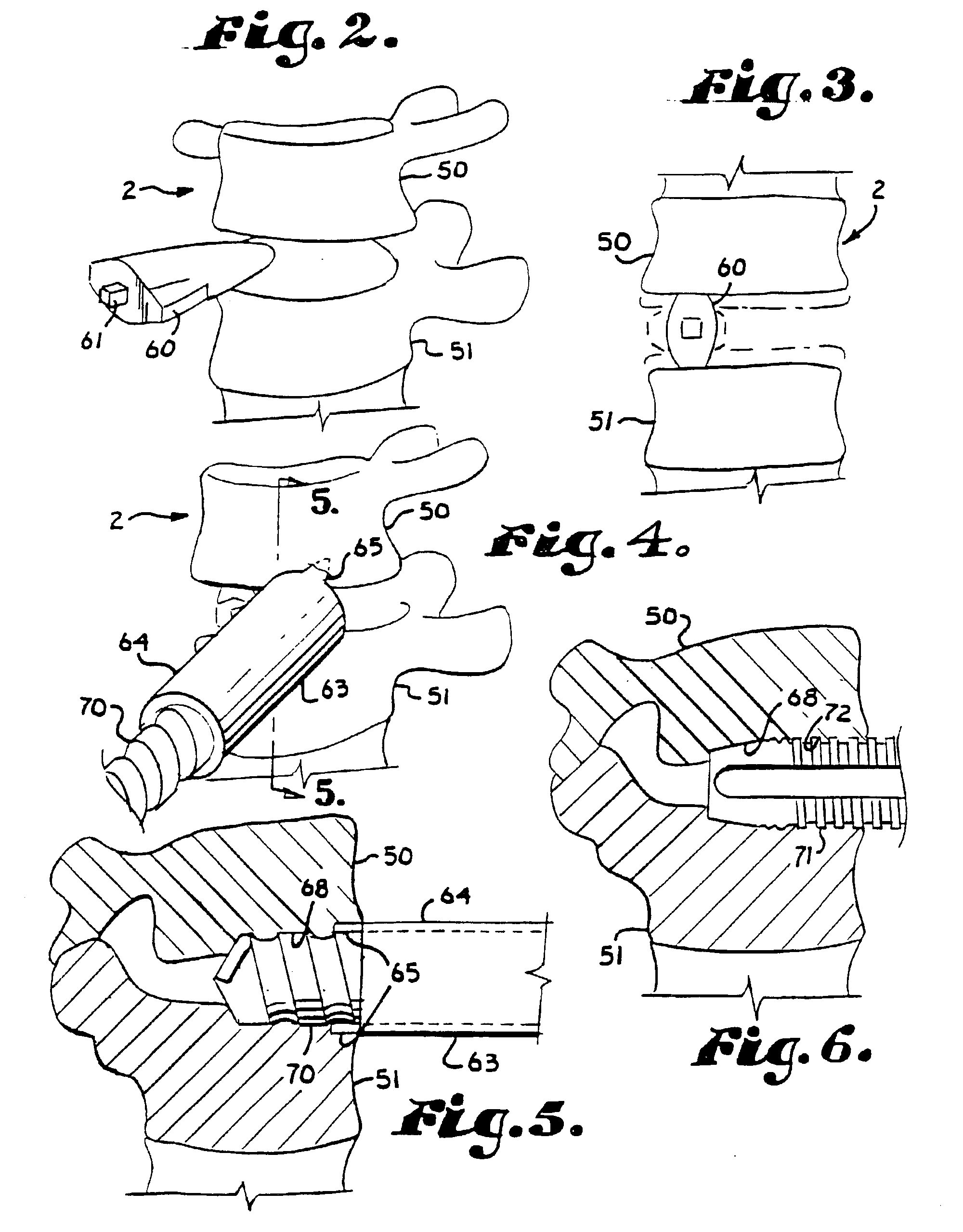
[0035]The reference numeral 1 generally represents a spinal stabilization and fusion enhancing apparatus or system 1 in accordance with the present invention shown in FIGS. 1 and 8 through 11a and showing installation of the apparatus 1 in FIGS. 1 through 11a in the spine 2 of a patient.

[0036]The fusion enhancing apparatus 1 includes a pair of bone receiving cages or implants 10 and 11 that are joined to a connecting plate 12 that joins a pair of end caps 15 and 16 by a pair of set screws 13 and 14 respectively.

[0037]The implants 10 and 11 are designed to be received in a circular bore, but have a somewhat rectangular cross-section with arcing at four opposite corners. Implants of the type illustrated are sold in the marketplace by Spine-Tech Inc. and other manufacturers of spinal fusion type implants. It is foreseen that pairs of implants of a wide range of shapes and constructed of a wide range of materials may be utilized in the invention, provided that the implants are positiona...

second modified embodiment

[0064]Illustrated in FIGS. 14, 15 and 16 is a spinal stabilization apparatus in accordance with the invention, generally identified by the reference numeral 201 and used in conjunction with a spine 202.

[0065]The apparatus 201 includes a first pair of implants 205 and 206 joined by a first connecting member 207 and a second pair of implants 208 and 209 joined by a second connecting member 210. The implants 205, 206, 208 and 209 are similar to the implants of the previous embodiments in that each contains bone and has windows 212 or similar openings extending between an interior chamber holding the bone and an exterior.

[0066]The implants 205, 206, 208 and 209 are different in comparison to those of the previous embodiment in the shape and method of implantation thereof. The implants 205, 206, 208 and 209 illustrate implant types that are placed between bones 220, 221 and 222 by striking or pushing, sometimes referred to as tap-in type herein, as opposed to being secured by screwing in...


PUM


Abstract

An apparatus for stabilizing and promoting fusion between adjacent vertebrae includes at least a pair of implants to promote bone growth and to fuse with vertebral bone. The implants are joined by a connector. Preferably the implants are inserted into receiving bores in a non-parallel configuration and/or the connector joins the implants so as to bias the implants to a non-parallel configuration. A pair of connecting members also preferably secure the implants to each of the adjacent vertebrae. A method of using the apparatus provides for stabilizing between vertebrae where the original cushioning disc has deteriorated or become damaged. The implants are connected together. Also in the method, the implant receiving bores are non-parallel and/or the implants are biased to non-parallel configurations by joining the implants to the connecting element so as to reduce the inadvertent disturbance of the implants from the receiving bores and to further stabilize the implants overall during the fusion process.

Description

[0001]The present application is one of three related copending applications including application entitled Inflatable MEMS Evaporation Gas Cell Structure System Ser. No. 10 / 166,882 filed Jun. 11, 2002, application entitled Inflatable Gas Cell Structure Deploying Method, Ser. No. 10 / 166,881, filed Jun. 11, 2002, and having a terminal disclaimer, and application entitled Inflatable MEMS Ablation Gas Cell Structure System, Ser. No. 10 / 171,715 filed on Jun. 12, 2002 and having a terminal disclaimer, which three applications all having a common named inventor and all assigned to a common assignee.BACKGROUND OF THE INVENTION[0002]The present application is directed to an apparatus and method of stabilizing the spine by placement of implants between effected vertebrae which result in fusion of the vertebrae. In particular, the present application is directed to an apparatus and method of improving the stabilization of the implants during the fusion process by linking the implants that are...

Claims


Application Information

Patent Timeline
IPC IPC(8): A61F2/44A61B17/17A61B17/16A61B17/68A61B17/70A61B17/86A61B17/80A61F2/00A61F2/30A61F2/28A61F2/46A61B17/02
CPCA61F2/446A61F2/447A61B17/1757A61B17/7059A61B17/8085A61B17/86A61B2017/0256A61F2/30744A61F2/30767A61F2/30965A61F2/442A61F2002/2835A61F2002/30143A61F2002/30153A61F2002/30158A61F2002/30168A61F2002/30235A61F2002/30283A61F2002/30329A61F2002/30433A61F2002/30507A61F2002/30517A61F2002/30774A61F2002/30777A61F2002/30785A61F2002/30787A61F2002/30789A61F2002/30795A61F2002/3085A61F2002/30858A61F2002/4475A61F2002/448A61F2002/449A61F2002/4638A61F2220/0025A61F2220/0041A61F2230/0017A61F2230/0019A61F2230/0026A61F2230/0043A61F2230/0063A61F2230/0069A61F2310/00017A61F2310/00131A61F2310/00137A61F2002/3028A61F2002/30593
Inventor JACKSON, ROGER P.
Owner WARSAW ORTHOPEDIC INC
Why Eureka
Try Eureka