Fluid filter

a filter and fluid technology, applied in the field of fluid filters, can solve the problems of inability to securely achieve fluid purification, increase costs, disadvantages, etc., and achieve the effect of reducing running costs

Inactive Publication Date: 2005-08-09
INOAC CORP
View PDF9 Cites 31 Cited by
  • Summary
  • Abstract
  • Description
  • Claims
  • Application Information

AI Technical Summary

Benefits of technology

[0011]The present invention proposed in view of the problems inherent in the prior art described above and with a view to solving them well is directed to providing a fluid filter having a case body and a filter medium housed in a holder defined in the case body, in which the filter medium is suitably compres

Problems solved by technology

However, it involves a problem that extraneous substances S smaller than the air gaps are not captured but pass through the filter medium 70, resulting in the failure of securely achieving purification of the fluid.
However, the use of at least two kinds of filter mediums 70(70A and 70B) of different densities requires operations of shaping each filter medium 70 into a required shape and a required size, leading to cost increase

Method used


Image

  • Fluid filter
  • Fluid filter
  • Fluid filter

Examples


first embodiment

(Variation of First Embodiment)

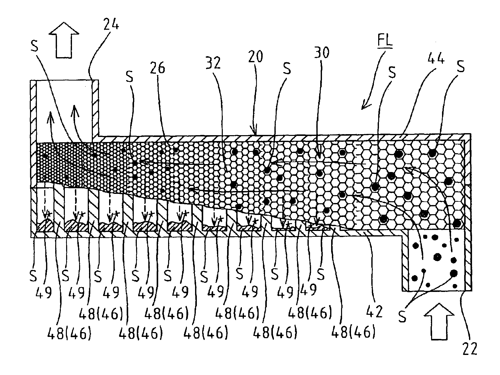
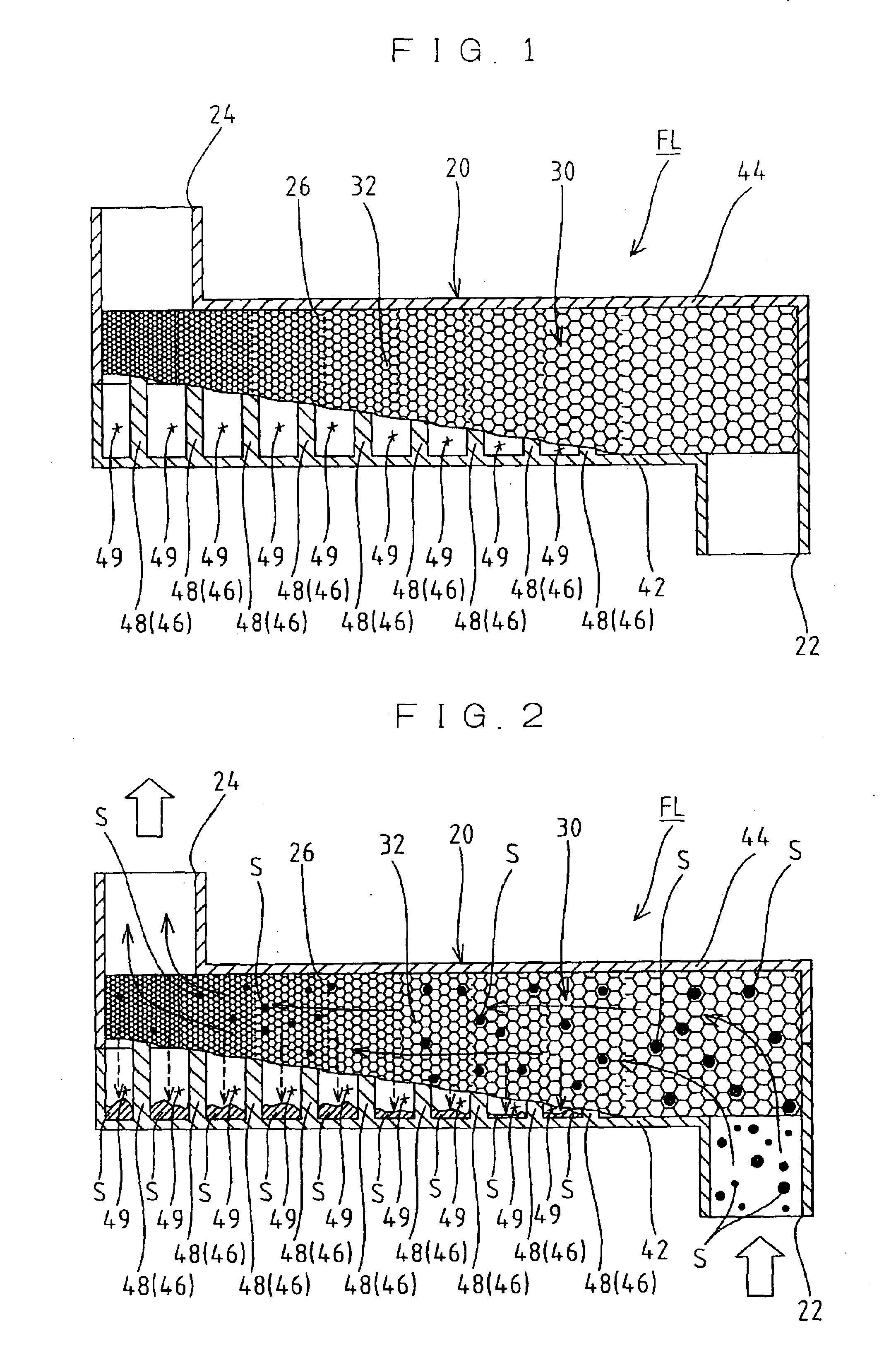
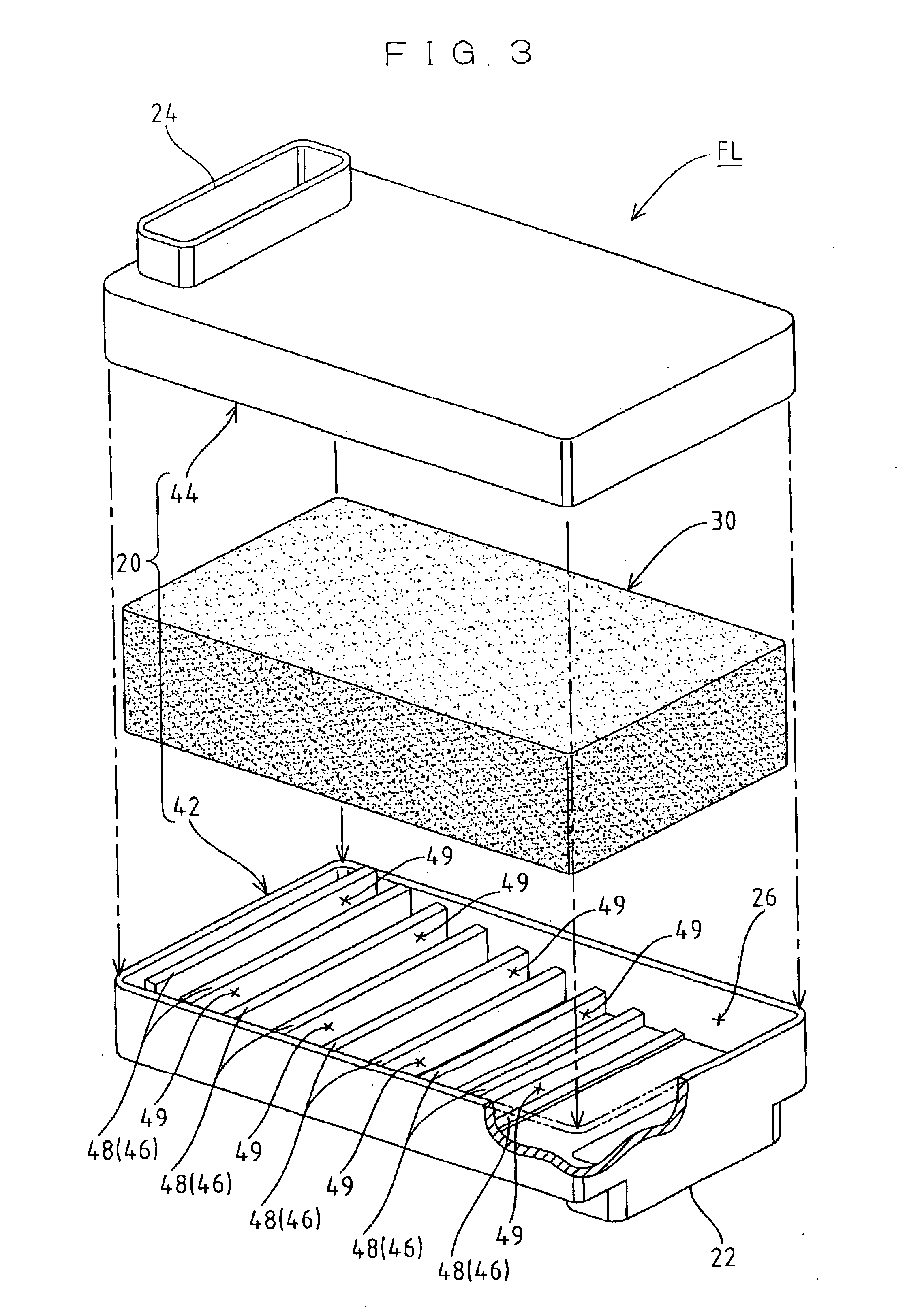
[0057]FIG. 5 is a vertical cross-sectional side view of the fluid filter FL according to a variation of the first embodiment, which is in operation. In the fluid filter FL illustrated in the first embodiment, a necessary number of pressing portions 46 (ribs 48) are formed on the internal wall surface of the filter case 20 such that they are arranged parallelwise on one side of the holder 26 (on the internal bottom surface of the first half 42 only) to compress the filter medium 30 from one side and obtain the compressed region 32. Meanwhile, in the fluid filter FL according to the variation, a necessary number of pressing portions 46 (ribs 48) are formed on the internal wall surface of the filter case 20 such that they are arranged parallelwise on both sides of the holder 26 (on the internal bottom surface of the first half 42 and on the internal top surface of the second half 44) to compress the filter medium 30 from both sides and obtain the compress...

second embodiment

(Variation of Second Embodiment)

[0071]In the fluid filter FL shown in the second embodiment, a necessary number of pressing portions 46 (ridges 52) are formed on the internal wall surface of the filter case 20 such that they are arranged parallelwise on one side of the holder 26 (on the internal bottom surface of the first half 42 only) to compress the filter medium 30 from one side and obtain the compressed region 32. However, in order to form a compressed region 32 having an increased rate of capturing extraneous substances S in a filter medium 30 as desired by pressing the pressing portions 46 formed in the filter case 20 against the filter medium housed in the holder 26, there can also be employed an embodiment (not shown), in which the pressing portions 46 (ridges 52) are formed on the internal surface of the filter case 20 such that they are arranged on both sides of the holder 26 (on the internal bottom surface of the first half 42 and on the internal top surface of the secon...

third embodiment

(Third Embodiment)

[0076]FIG. 14 is a vertical cross-sectional side view showing schematically a fluid filter according to a third embodiment of the present invention; FIG. 15 is a horizontal cross-sectional plan view showing schematically the fluid filter shown in FIG. 14; FIG. 16 is an exploded perspective view of the fluid filter. The fluid filter FL according to the third embodiment is provided with a filter case (case body) 110 and a filter medium 120. The filter case 110 has an inlet 112 and an outlet 114 for a fluid at required positions respectively and also has a holder116 defined therein to communicate with the inlet 112 and the outlet 114. The filter medium 120 is made of a porous material having an appropriate flexibility and a uniform density and is removably housed in the holder 116. While urethane foam having an open-cell structure is exemplified as the porous material in this embodiment, other porous materials employable here as the filter medium 120 include synthetic...


PUM

PropertyMeasurementUnit
Structureaaaaaaaaaa
Sizeaaaaaaaaaa
Densityaaaaaaaaaa

Abstract

A fluid filter is provided with a case body defining therein a holder and having pressing portions formed on the internal wall surface of the case body. The pressing portions can compress a filter medium housed in the holder. The pressing portions are pressed against the filter medium housed in the holder to compress it and form a compressed region at a desired position of the filter medium, where the rate of capturing extraneous substances is increased. Thus, even if various sizes of the extraneous substances are contained in a fluid introduced through the inlet into the holder, the filter medium can capture the extraneous substances in its entirety. The degree of compression of the compressed region in the filter medium changes depending on the height of each pressing portion.

Description

BACKGROUND OF THE INVENTION[0001]1. Field of the Invention[0002]The present invention relates to a fluid filter. More particularly, the present invention relates to a fluid filter provided with a case body and a filter medium; the case body having an inlet and an outlet for a fluid at required positions respectively and also a holder defined therein to communicate with the inlet and outlet; the filter medium being made of a porous material having an appropriate flexibility and a uniform density and being removably housed in the holder. A fluid introduced through the inlet into the holder is allowed to pass through the filter medium where fine extraneous substances contained in the fluid are captured, and the resulting purified fluid is discharged through the outlet.[0003]2. Description of the Related Art[0004]As shown in FIG. 23, many of air purifiers, automobile engines, hydraulic cylinders and various kinds of other apparatuses which utilize gaseous bodies such as air and other ga...

Claims


Application Information

Patent Timeline
IPC IPC(8): B01D35/30B01D46/10
CPCB01D35/30B01D46/10B01D2201/06B01D2201/188B01D2275/203B01D2275/305B01D2275/403Y10S55/42
Inventor SHIRAISHI, TERUOHORIO, FUMINORI
Owner INOAC CORP
Why Eureka
Try Eureka