Method and apparatus for directly sampling a fluid for microfiltration

a microfiltration and fluid technology, applied in the field of methods and apparatus for directly sampling a fluid for microfiltration, can solve the problems of specimen transfer, apparatus does current approaches to specimen transfer do not solve all the problems of automation

Inactive Publication Date: 2005-08-09
BIODATA
View PDF73 Cites 22 Cited by
  • Summary
  • Abstract
  • Description
  • Claims
  • Application Information

AI Technical Summary

Benefits of technology

[0026]In a further preferred embodiment of the process, the filtration cell further comprises an air inlet port having a passageway therethrough and adapted to receive air from a pressure source, and the method further comprises pressurizing the container after fluid to be filtered is initially transferred to the reservoir to ensure that a substantial amount of the fluid flows from the container to the reservoir.

Problems solved by technology

There is, however, a remaining problem namely the problem of specimen transfer.
Despite its advantages, such apparatus does not solve all the problems of automation.
Current approaches to specimen transfer does not solve all the problems of automation.
Current approaches to specimen transfer severely limit automation.
This translates into increased equipment costs as well as biohazardous waste transfer and disposal costs.
Other costs include operating costs such as reagent fluid, disposable tubing, waste containers and waste transfer and disposal expenses.

Method used


Image

  • Method and apparatus for directly sampling a fluid for microfiltration
  • Method and apparatus for directly sampling a fluid for microfiltration
  • Method and apparatus for directly sampling a fluid for microfiltration

Examples


Embodiment Construction

[0040]Certain terminology is used herein for convenience only and is not be taken as a limitation on the present invention. The words “right,”“left,”“outwardly” and “inwardly”, and “down” and “up”, designate directions in the drawings to which reference is made. The words “proximal” and “distal” refer to directions away from and closer to, respectively, the interior of the filtration cell according to the present invention. The terminology includes the words above specifically mentioned, derivatives thereof, and words of similar import.

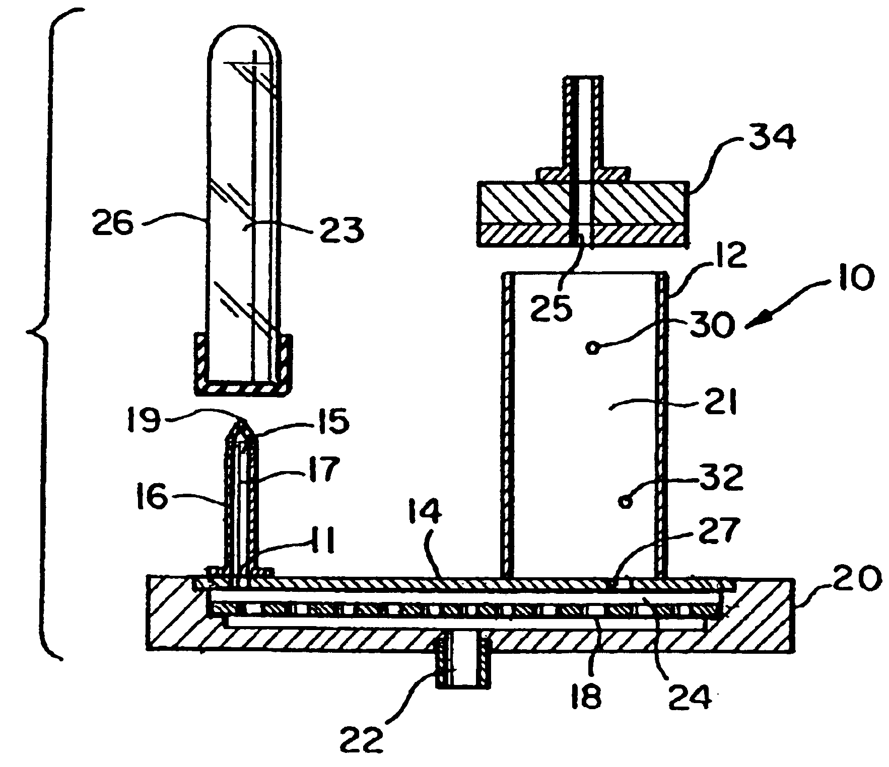
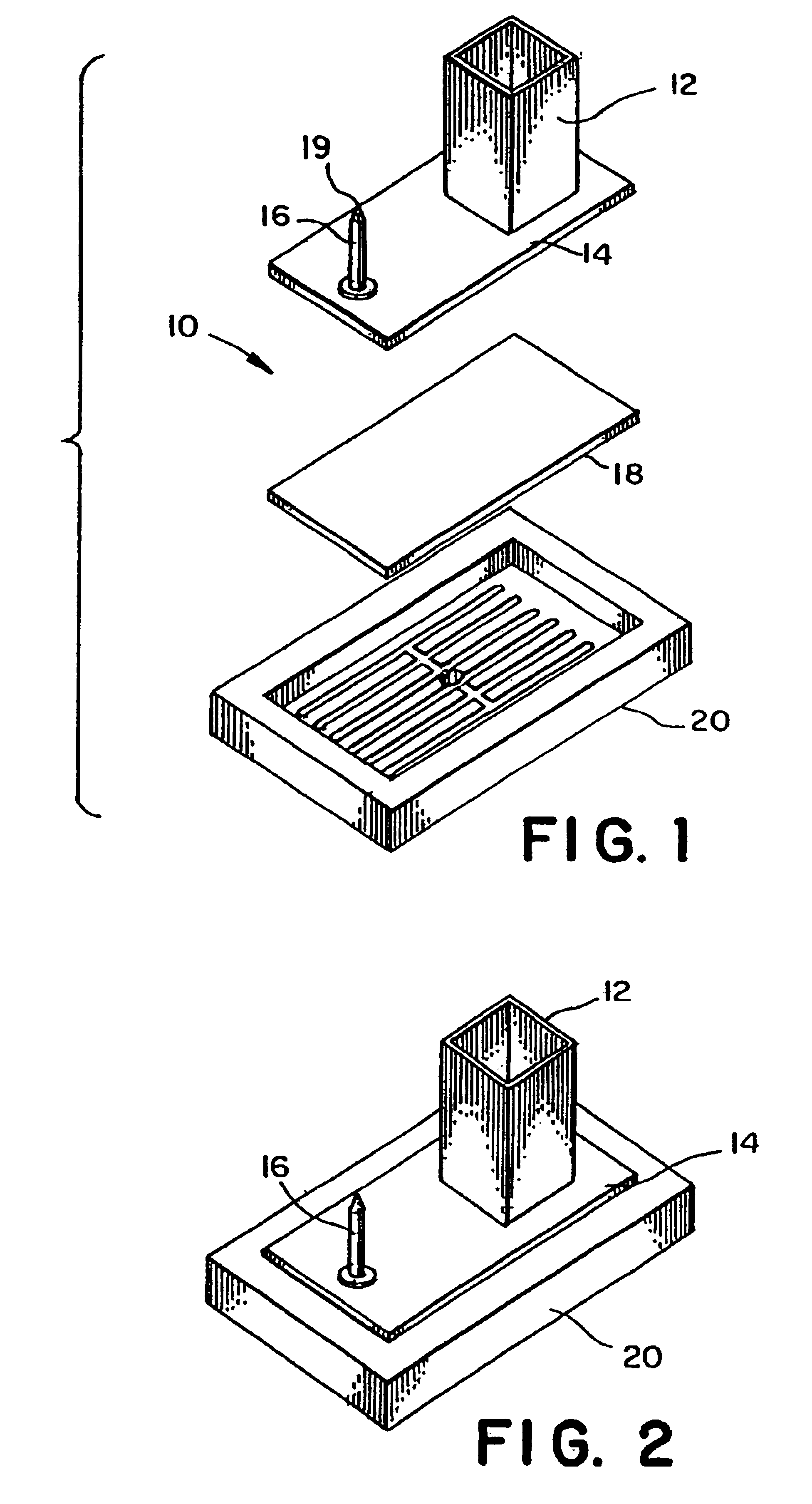
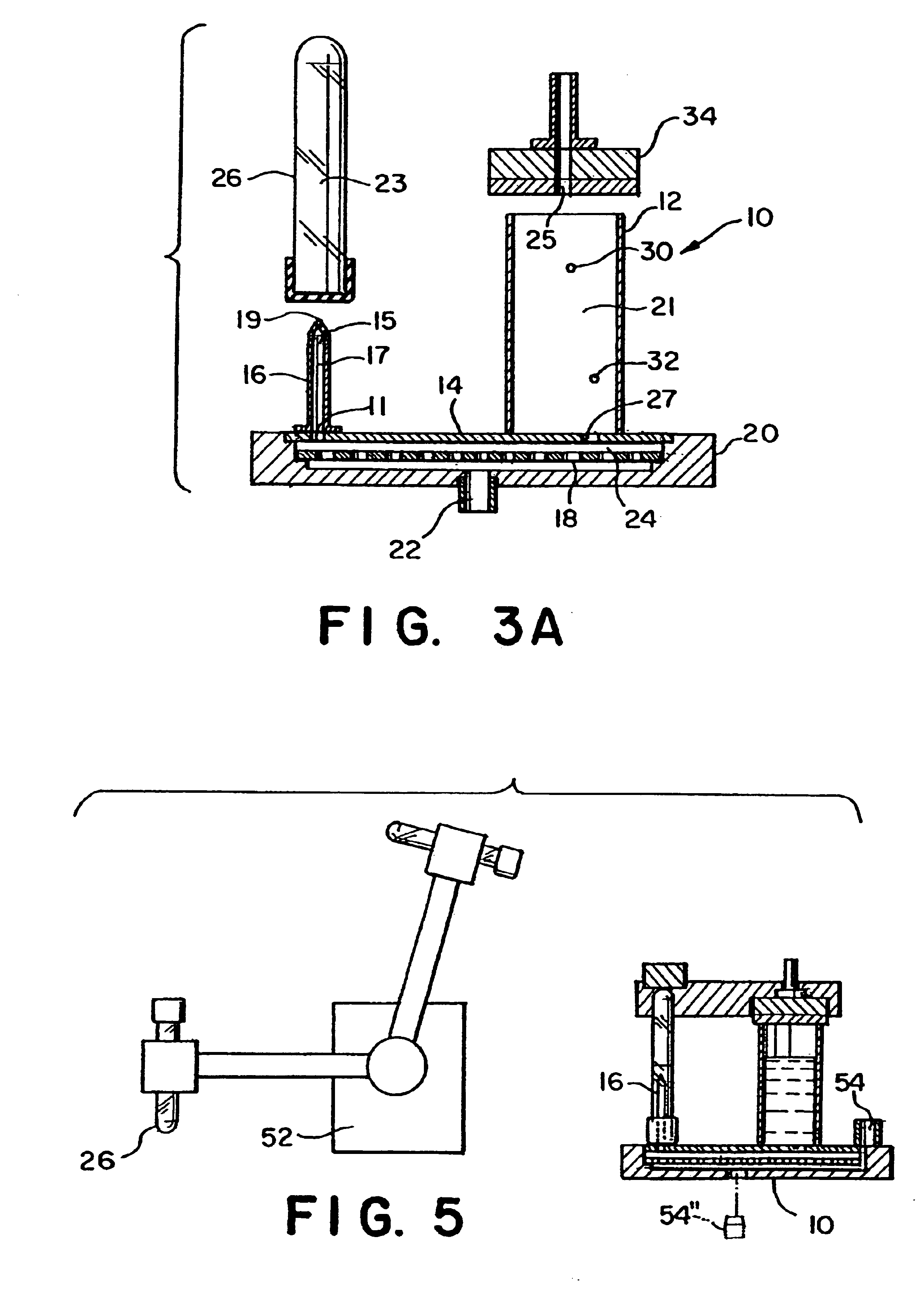
[0041]The following describes preferred embodiments of the invention. However, it should be understood, based on this disclosure, that the invention is not limited by the preferred embodiments described herein. Referring now to the drawings in detail, there is shown in FIGS. 1, 2, 3A, 4A-4C and 5, a preferred embodiment of a filtration system, filtration cell for direct sampling of a fluid from a container and a process for directly transferring a spe...


PUM

PropertyMeasurementUnit
sizeaaaaaaaaaa
volumeaaaaaaaaaa
volumeaaaaaaaaaa

Abstract

Filtration cells capable of direct sampling of a fluid from a container and which may be used for microfiltration of both small and large microvolumes of a fluid to be filtered are provided. Also a process for directly transferring a fluid to be filtered from a container to a filtration cell is described. The filtration cells have one or more reservoirs and are in communication with fluid in a container to be filtered through a piercing instrument connected to a base and support for a reservoir that receives the fluid to be filtered after it passed across a filter membrane. The filtration cell may then be pressurized and vented to allow fluid to be filtered to reciprocally and tangentially pass across a filter membrane between either a container having a fluid to be filtered and a single reservoir for small volume filtrations or between two reservoirs after pressurizing a fluid to be filtered into the reservoirs from a container using a piercing instrument. Side wells for collecting samples from the bottom up from the filtration cell outlet are also provided as are a process incorporating automated equipment for transferring the container having fluid to be filtered to the piercing point for entry into the filtration cell.

Description

CROSS-REFERENCE TO RELATED APPLICATION[0001]This application is a continuation of U.S. patent application Ser. No. 10 / 068,331, filed Feb. 6, 2002, now U.S. Pat. No. 6,740,240, which is a divisional of U.S. patent application Ser. No. 09 / 580,987, filed May 30, 2000, now U.S. Pat. No. 6,398,956, which claims the benefit of U.S. Provisional Application No. 60 / 136,668, filed May 28, 1999. The entire disclosures of U.S. patent application Ser. Nos. 10 / 068,331 and 09 / 580,987, as well as U.S. Provisional Application No. 60 / 136,668 are incorporated herein by reference as if fully set forthBACKGROUND OF THE INVENTION[0002]Microfiltration is known as are filtration cells that produce a filtrate through microfiltration. U.S. Pat. No. 4,818,493 discloses a filtration cell for separating a filtrate from a fluid, such as plasma from blood, by means of micro-filtration. U.S. Pat. No. 5,000,923 discloses a particular filtration cell having application in the art of filtering plasma from blood by a ...

Claims


Application Information

Patent Timeline
Patent Type & Authority Patents(United States)
IPC IPC(8): B01D61/18B01D65/08B01D61/14B01D65/00G01N1/00G01N33/49G01N1/28B01L99/00
CPCB01D61/147B01D65/08G01N1/4077G01N33/491G01N35/1079B01L3/502B01D61/18Y10T436/255B01D2321/2033B01D2321/2083B01L2300/0672B01L2300/0681B01L2300/0816B01L2400/0487B01L2400/049
Inventor COVILLE, WILLIAM E.ST. ONGE, DAVID M.
Owner BIODATA
Why Eureka
Try Eureka