Filtration using pressure vessel with multiple filtration channels

a technology of pressure vessel and filtration channel, which is applied in the direction of membranes, filtration separation, separation processes, etc., can solve the problems of high energy cost associated with producing the required pressure across the membrane, excessive fouling of the membrane, and often polluted water, so as to reduce the coupling ratio

Inactive Publication Date: 2005-09-13
DESALNATE INC
View PDF3 Cites 46 Cited by
  • Summary
  • Abstract
  • Description
  • Claims
  • Application Information

AI Technical Summary

Benefits of technology

[0016]In preferred embodiments the feed fluid flow path comprises an annular space between the inner casings and the filters contained in such casings, and in more preferred embodiments the annular space is substantially continuous past multiple filters of the same inner casing. The inner casings may advantageously have openings that fluidly communicate with the lumen of the outer casing, thereby reducing the ratio of couplings relative to the number of filters (the coupling / filter ratio).

Problems solved by technology

Many areas of the world have insufficient fresh water for drinking or agricultural uses, and in other areas where plentiful supplies of fresh water exist, the water is often polluted with chemical or biological contaminants, metal ions and the like.
There are several problems associated with reverse osmosis (RO), including excessive fouling of the membranes and high energy costs associated with producing the required pressure across the membranes.
These two problems are interrelated in that most or all of the known RO units require flushing of the membranes during operation with a relatively large amount of feed liquid relative to the amount of permeate produced.
Because only a portion of the water being pumped is recovered as purified water, energy used to pump the excess brine is wasted, creating an inherent inefficiency.
Unfortunately, known work exchange pumps employ relatively complicated piping, and in any event are discontinuous in their operation.
These factors add greatly to the overall cost of installation and operation.
A system according to FIG. 1 may be relatively energy efficient, but is still somewhat complicated from a piping standpoint.
In a large system such fluid connections may be expensive to maintain, especially where filtration elements in the permeators need to be replaced every few years.
It would be advantageous to reduce the ratio of couplings relative to the number of filters still further, but five membranes is usually considered to be the upper limit in an Eckman type system because pressure drops past the several membranes reduce the feed fluid pressure to an undesirable degree.

Method used


Image

  • Filtration using pressure vessel with multiple filtration channels
  • Filtration using pressure vessel with multiple filtration channels
  • Filtration using pressure vessel with multiple filtration channels

Examples


Embodiment Construction

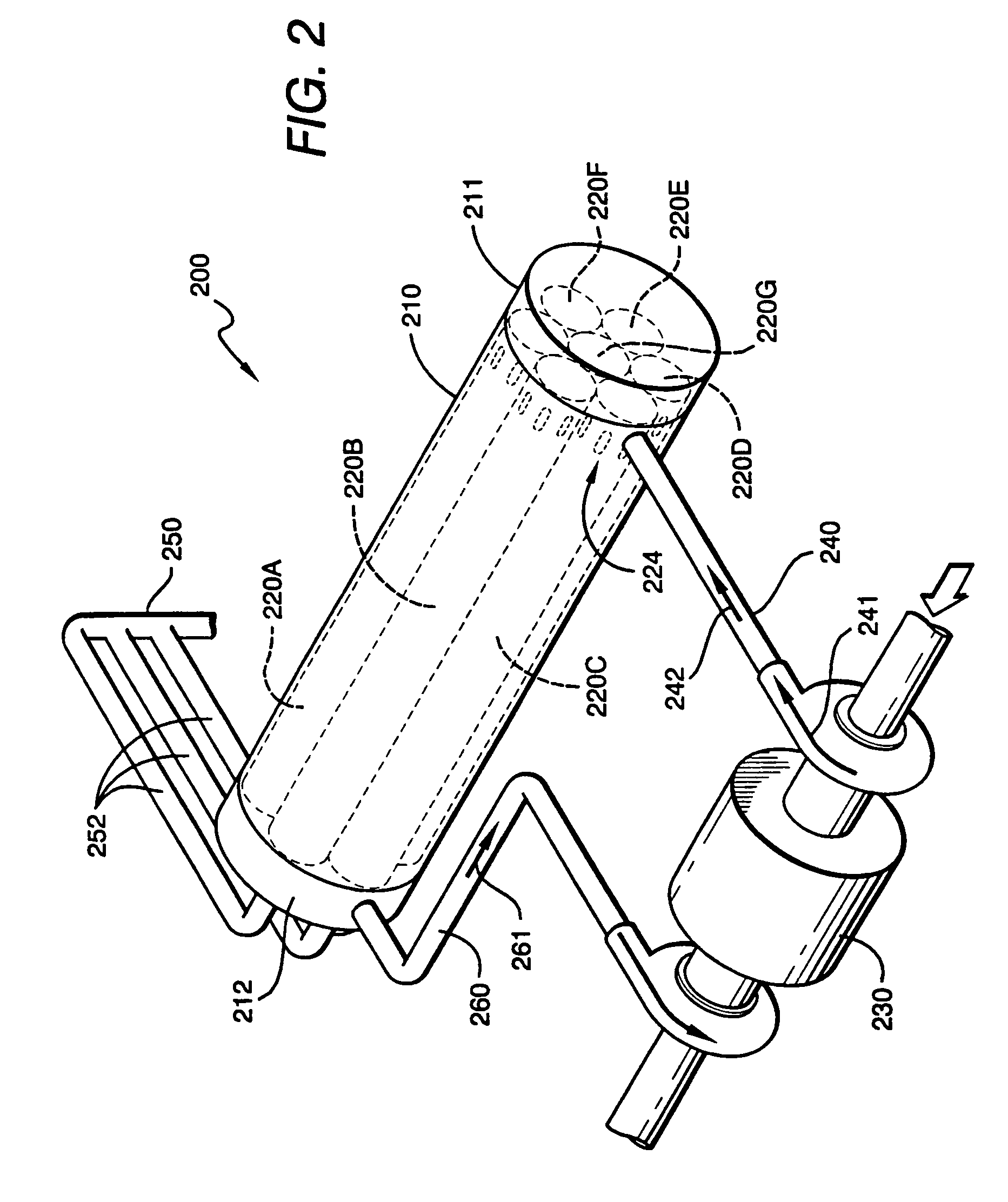
[0026]In FIG. 2 a preferred filtration system 200 generally comprises an outer casing 210 containing multiple internal casings 220A–220G in which filters (not shown) are disposed, and a pump / energy recovery unit 230. Feed fluid is fed to the end plate subassembly 211 of the outer casing 210 from feed fluid line 240, and passes into the internal casings 220A–220G via openings 224 in the walls of the internal casings 220A–220G. The feed fluid is filtered by the filters, with permeate being removed from the internal casings 220A–220G at end plate subassembly 212 via permeate manifold 252 and permeate line 250, and waste fluid being removed from the internal casings 220A–220G via waste fluid line 260. Arrows 241 and 242 depict fluid flow in line 240, and arrow 261 depicts fluid flow in line 260.

[0027]The outer casing 210 advantageously comprises a hollow cylinder, although other elongated shapes including those having triangular, rectangular, or octagonal cross sections are also contemp...


PUM

PropertyMeasurementUnit
lengthaaaaaaaaaa
diameteraaaaaaaaaa
pressure dropaaaaaaaaaa

Abstract

A filtration system includes an outer casing (210) that houses a plurality of elongated inner casings (220A–220F), which in turn house a plurality of filtration membranes. The outer casing, inner casing, and filtration membranes are disposed relative to one another to provide a three-flow channel system that provides additional feed fluid at one or more membrane couplings between membranes of the same inner casing. Ths arrangement defines a feed fluid flow path in which a feed fluid exiting from an upstream filter into a downstream filter is diluted by additional feed fluid.

Description

[0001]This application claims priority to provisional patent application No. 60 / 136,739 filed May 27, 1999, which is incorporated by reference herein in its entirety.FIELD OF THE INVENTION[0002]The present invention relates generally to filtration of fluids, including especially filtration of water.BACKGROUND[0003]There is a great worldwide demand for purified fluids, one of the most commercially important of which is production of fresh water. Many areas of the world have insufficient fresh water for drinking or agricultural uses, and in other areas where plentiful supplies of fresh water exist, the water is often polluted with chemical or biological contaminants, metal ions and the like. There is also a continuing need for commercial purification of other fluids such as industrial chemicals and food juices. U.S. Pat. No. 4,759,850, for example, discusses the use of reverse osmosis for removing alcohols from hydrocarbons in the additional presence of ethers, and U.S. Pat. No. 4,959...

Claims


Application Information

Patent Timeline
Patent Type & Authority Patents(United States)
IPC IPC(8): B01D61/10B01D61/08B01D63/04B01D65/08B01D63/10B01D63/12B01D61/02B01D65/00
CPCB01D61/022B01D61/08B01D61/10B01D63/043B01D63/12B01D65/00B01D65/02B01D65/08B01D2321/10B01D2313/105B01D61/026
Inventor CHANCELLOR, DENNISJENSEN, JAMES
Owner DESALNATE INC
Why Eureka
Try Eureka