
Double membrane transducer protector

a technology of transducer protector and double membrane, which is applied in the direction of filtration separation, instruments, separation processes, etc., can solve the problems of increased risk of non-sterile procedures and poor connection between the different transducer protectors

Inactive Publication Date: 2006-07-04
JMS NORTH AMERICA
View PDF17 Cites 46 Cited by
  • Summary
  • Abstract
  • Description
  • Claims
  • Application Information

AI Technical Summary

Benefits of technology

"The present invention is a device that protects a transducer in a dialysis machine. It includes a protector that can be connected to a monitoring tube and a dialysis machine. The protector has two filters to prevent contamination. The device can be easily connected together using ultrasonic welding, heat sealing, or RF welding. The indicators can be a biological or chemical material that changes color upon contact with bodily fluid. The technical effect of this invention is to provide a reliable and efficient way to protect the transducer in a dialysis machine."

Problems solved by technology

However, drawbacks to these solutions include, but are not limited to, the fact that they are bulky to use, they offer increased risk of non-sterile procedures, and they generally employ poor connections between the different transducer protectors.

Method used


Image

  • Double membrane transducer protector
  • Double membrane transducer protector
  • Double membrane transducer protector

Examples


Embodiment Construction

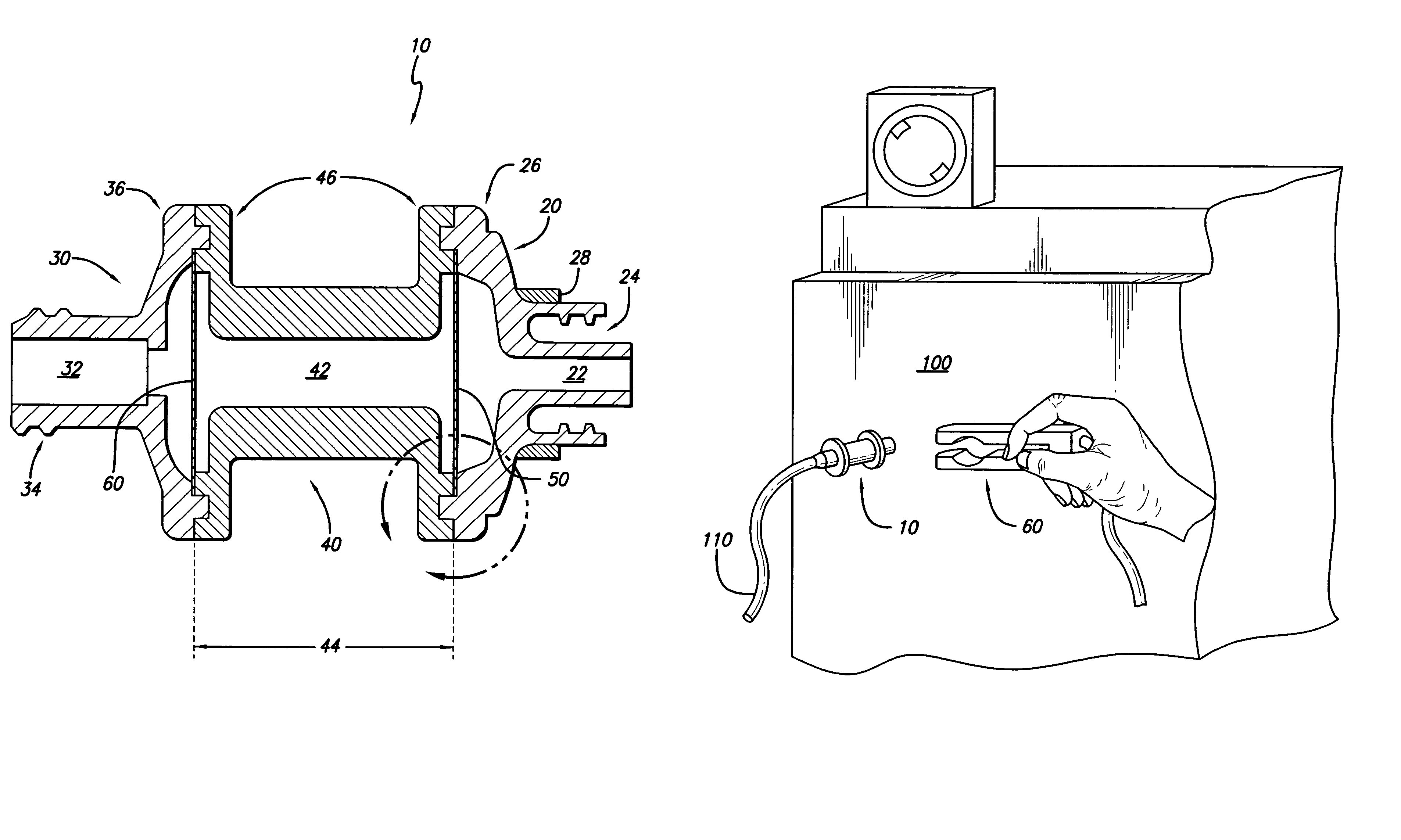
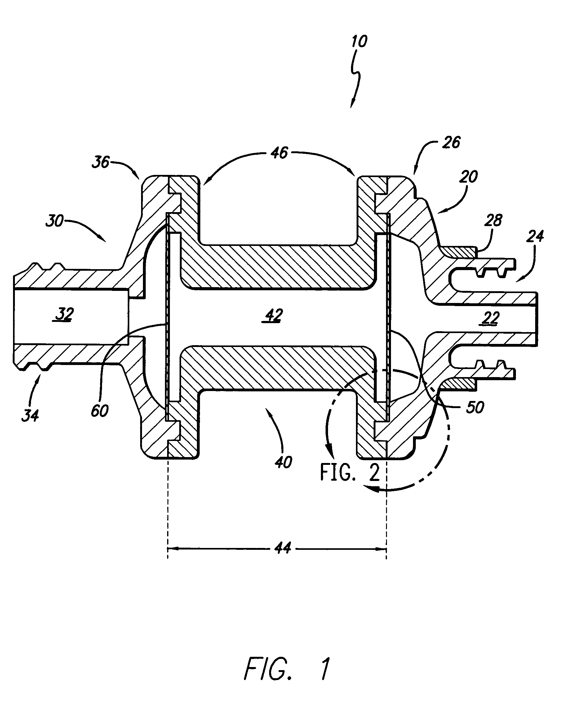
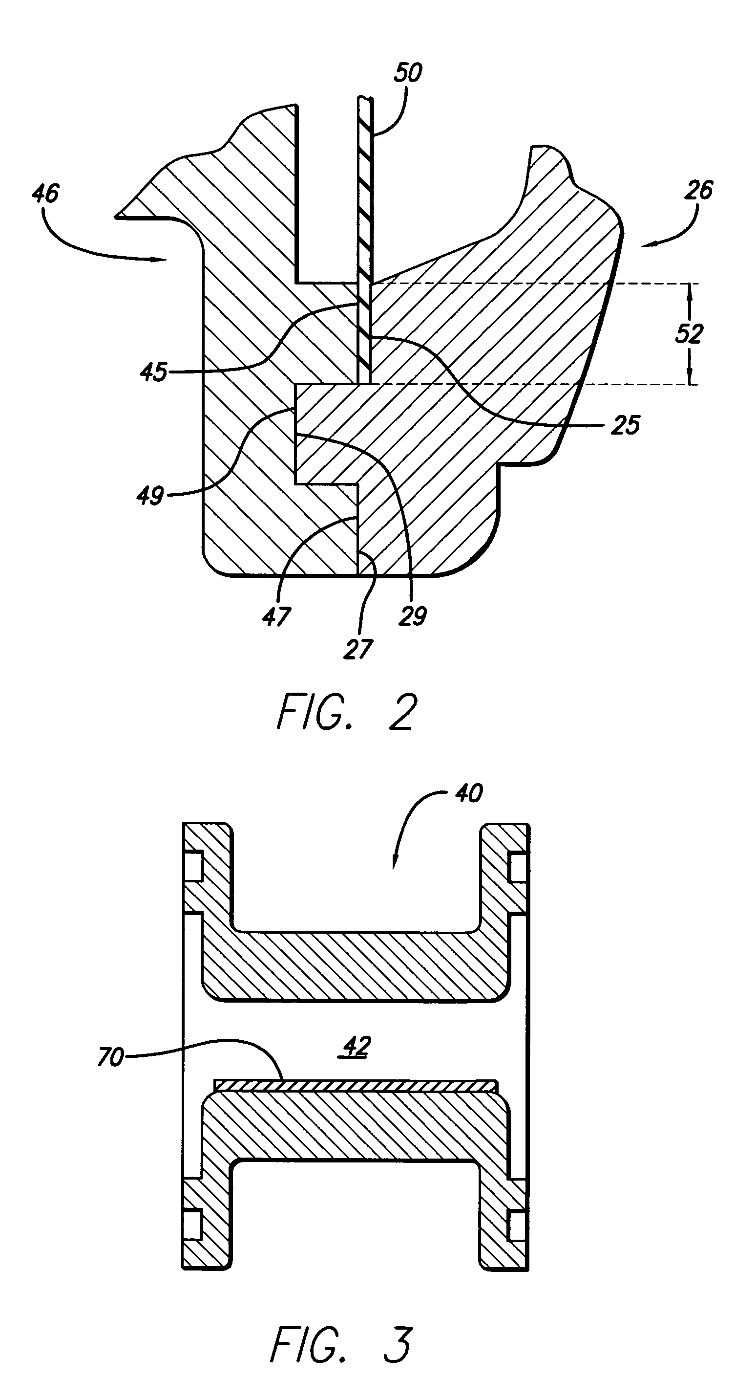
[0015]The following detailed description should be read with reference to the drawings, in which like elements in different drawings are identically numbered. The drawings, which are not necessarily to scale, depict selected preferred embodiments and are not intended to limit the scope of the invention. The detailed description illustrates by way of example, not by way of limitation, the principles of the invention. This description will clearly enable one skilled in the art to make and use the invention, and describes several embodiments, adaptations, variations, alternatives and uses of the invention, including what is presently believed to be the best mode of carrying out the invention.

[0016]The present invention is directed to a transducer protector containing more than one filter membrane so that detection of a breached or wetted membrane can lead to prevention of system contamination (in contradistinction to the prior art devices in which detection of a breached or wetted memb...


PUM

PropertyMeasurementUnit
distanceaaaaaaaaaa
lengthaaaaaaaaaa
sizeaaaaaaaaaa

Abstract

A transducer protector having at least two filter membranes. In one embodiment, the transducer protector includes a body between two tubular connectors, each of which has a lumen that may be axially aligned. The body lumen is separated from the lumen of each of the tubular connectors by a filter membrane. In one embodiment, the body is transparent and the body lumen has an indicator to alert a user that the filter membrane has been breached by a contaminant so that the user can take immediate steps to prevent further contamination of the system. The configuration of the transducer protector also facilitates the use of separate indicator devices, such as sensor clips.

Description

CROSS-REFERENCE TO RELATED APPLICATIONS[0001]Not applicable.STATEMENT REGARDING FEDERALLY SPONSORED RESEARCH OR DEVELOPMENT[0002]Not applicable.REFERENCE TO A COMPACT DISK APPENDIX[0003]Not applicable.BACKGROUND OF THE INVENTION[0004]Hemodialysis, the most frequently used method for treating advanced and chronic kidney failure consists of a continuous process of removing blood from a patient, cleansing the blood with a special filter mounted on a dialysis machine, and returning the cleansed blood back to the patient. During the hemodialysis procedure, a trained health-care professional will continuously monitor the arterial (pre- and / or post-pump) and venous pressure in the extracorporeal circuit. This is typically done through a tube positioned between the extracorporeal circuit and the dialysis machine. A transducer protector is an in-line sterile barrier and is recommended to be placed between the monitoring line and the dialysis machine. The main purpose of the transducer protec...

Claims


Application Information

Patent Timeline
Patent Type & Authority Patents(United States)
IPC IPC(8): G01L7/00A61M1/36G01L19/06
CPCA61M1/3639A61M1/3641G01L19/0636A61M2205/15A61M2205/16A61M2205/7536A61M2205/7527
Inventor TEUGELS, LUDWIG
Owner JMS NORTH AMERICA
Learn More