String instrument chinrest pad system

a chinrest and string instrument technology, applied in the field of chinrests, can solve the problems of impeded vibration, impeded vibration, and impeded vibration, and achieve the effect of maximum vibration

Inactive Publication Date: 2005-08-09
ANDERSON GARY L
View PDF15 Cites 21 Cited by
  • Summary
  • Abstract
  • Description
  • Claims
  • Application Information

AI Technical Summary

Benefits of technology

[0007]It is an object of the present invention to provide an improved chinrest pad system that can be used with a standard chinrest that securely holds the chinrest on the instrument in an optimal position for maximum vibration.
[0008]It is another object of the present invention to provide such a pad system that prevents the chinrest from sliding on the instrument while being played with minimal compression forces applied to the instrument.
[0009]It is another object of the present invention to provide such a pad system that prevents the metal rods used with the clamping elements from contacting the upper and lower edges and impeding vibration and potentially causing damage.
[0010]These and other objects of the invention are met by a chinrest pad system disclosed herein designed to securely hold a standard chinrest used on a string instrument that minimizes the clamping pressure and dampening of vibration, and prevents damage by preventing the metal components from touching the sides of the instrument. The system includes an upper resilient pad disposed between the support surface of the chinrest member and the top angled surface of the instrument, and at least one lower resilient pad disposed between the lower flange on the lower metal rod and the bottom angled surface of the instrument. The upper and lower pads are specifically designed to partially bend around and engage the instrument's upper and lower edges, respectively. Each pad also includes a rear extending lip that extends rearward and prevents the metal rods from contacting the upper and lower edges. Each pad includes an inside surface designed to match the curvature of instrument's surface immediately adjacent to the edge. The opposite outside surface of each pad is designed to match the angle of the adjacent surface on the chinrest member and flange. The width of each pad is sufficient so that each pad is centered over the sidewall of the instrument so that the compression forces exerted by the support surface and flange are aligned with the sidewall's transverse axis.

Problems solved by technology

Anything that clamps onto the body of the instrument, particularly the top and bottom surfaces, will dampen or impede vibration.
When the flat pad rests on the flat region and onto the top surface of the instrument, vibration is impeded.
When the chinrest member slides inward, the upper and lower metal rods, upon which the turnbuckle rotates, contact the upper and lower edges of the instrument, which will impede vibration and can potentially cause damage to the instrument.

Method used


Image

  • String instrument chinrest pad system
  • String instrument chinrest pad system
  • String instrument chinrest pad system

Examples


Embodiment Construction

)

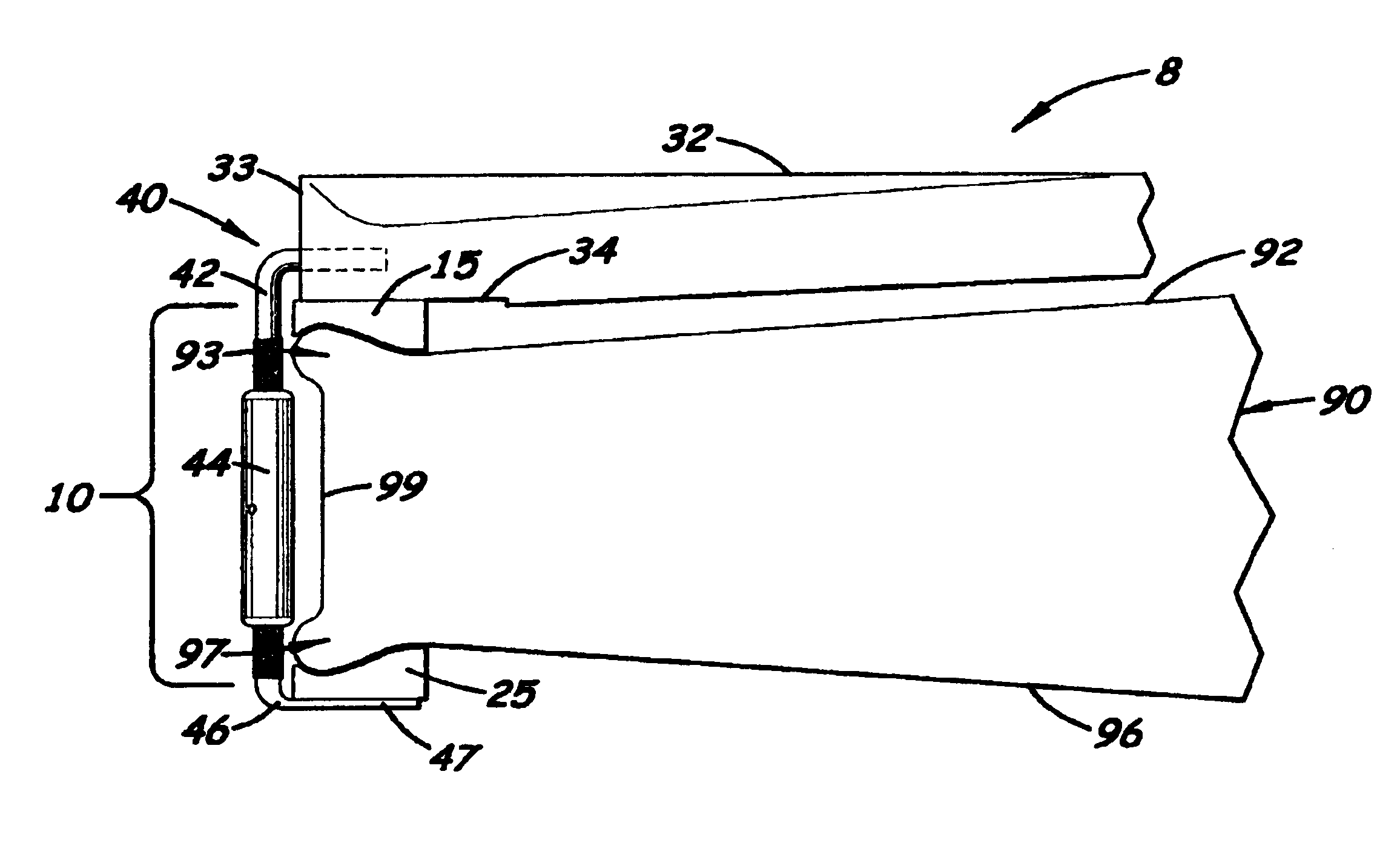
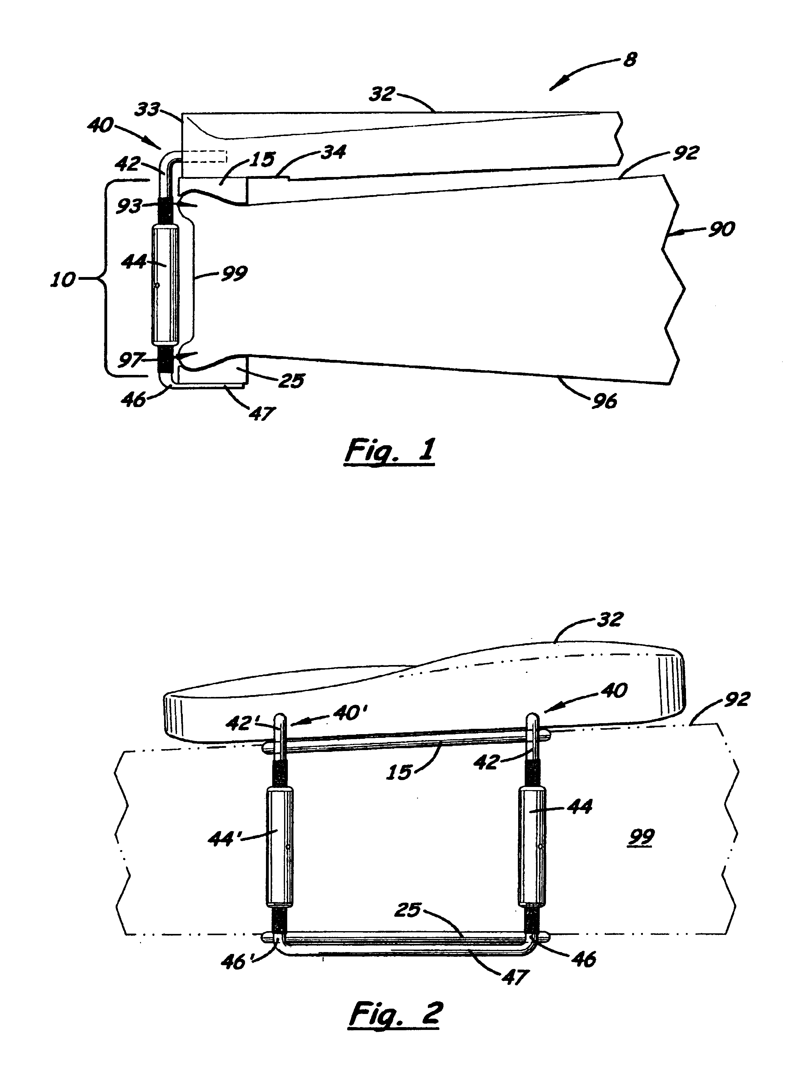
[0018]There is shown in the accompanying FIGS. a string instrument chinrest pad system 10 designed to be mounted on the rear surface of a string instrument 90, such as a violin, that overcomes the problems associated with chinrest designs found in the prior art.

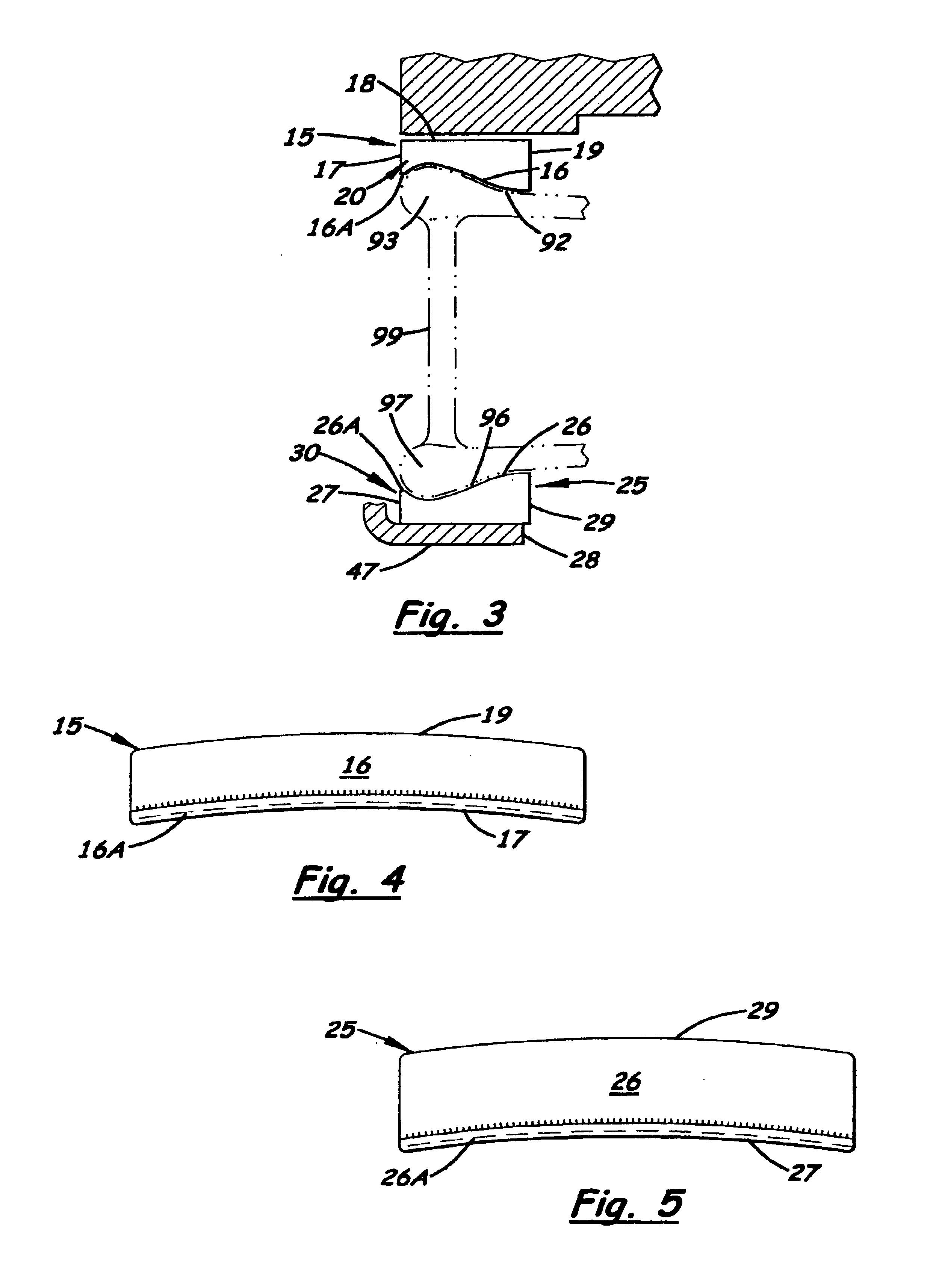
[0019]The system 10 includes an upper pad 15 and a lower pad 25 specifically designed to be used under the flat support surface 34 found on a typical chinrest member 32 and over the lower flange 47 used with a standard clamping element 40 used with the string instrument 90, respectively. The pads 15, 25 are specifically designed to partially engage the instrument's upper and lower edges 93, 97 and to conform to the adjacent top and bottom surfaces 92, 96 prior to applying a compression force so that the chinrest member 32 does not move. The outside surfaces 18, 28 of the pads 15, 25 are also designed to match the adjacent surfaces of the support surface 34 and the lower flange 47, respectively, to prevent movement of the chi...


PUM


Abstract

A chinrest pad system designed to hold a standard chinrest used with a string instrument that minimizes dampening of vibration and prevents damage caused by the metal components touching the edges of the instrument. The system includes pads located under the support surface of the chinrest member and on top of the lower lip plate used on the lower clamping member. The pads are specifically designed to partially engage the instrument's upper and lower edges and match the curvature of instrument surface immediately adjacent to the edge. Each pad also includes a rear extending lip that bends slightly around the upper or lower edge and extends rearward to prevent the metal rods used with the turnbuckles from contacting the rear surface. During assembly, the pads are positioned over the upper and lower edges so that the compression forces exerted by the support surface and the lower lip plate are centrally located over the sidewall transverse axis, thereby minimizing dampening of vibration.

Description

BACKGROUND OF THE INVENTION[0001]1. Field of the Invention[0002]This invention pertains to musical instruments, and more particularly to chinrests used with string instruments.[0003]2. Description of the Related Art[0004]The violin, in the most general sense, is a musical instrument that vibrates when played. The degree of vibration and resonance of the instrument is directly related to the degree that the wood is allowed to vibrate freely. Anything that clamps onto the body of the instrument, particularly the top and bottom surfaces, will dampen or impede vibration.[0005]A chinrest is a traditional part of a violin or viola, which allows the player to rest his or her chin while playing, without the chin touching the instrument. Normally, the chinrest includes a black, curved chinrest member made of plastic or wood that is positioned over the top surface of the instrument. The chinrest member is held in position by two clamping elements. Each clamping element includes an upper metal...

Claims


Application Information

Patent Timeline
Patent Type & Authority Patents(United States)
IPC IPC(8): G10D1/00G10D1/02G10G5/00G10D3/00G10D3/18
CPCG10D3/18
Inventor ANDERSON, GARY L.
Owner ANDERSON GARY L
Why Eureka
Try Eureka