Positioning device having dynamically isolated frame, and lithographic device provided with such a positioning device

a positioning device and dynamic isolation technology, applied in the direction of process and machine control, printing, instruments, etc., can solve the problem of reducing the frequency response of the stage, and achieve the effect of reducing unwanted moments of force (i.e., torque)

Inactive Publication Date: 2005-08-09
NIKON CORP
View PDF117 Cites 98 Cited by
  • Summary
  • Abstract
  • Description
  • Claims
  • Application Information

AI Technical Summary

Benefits of technology

[0008]A precision motion stage mechanism includes the stage itself which moves in the X-Y plane on a flat base. The stage is laterally surrounded by a “window frame” guide structure which includes four members attached at or near their corners to form a rectangular structure. The attachments are flexures which are a special type of hinge allowing movement to permit slight distortion of the rectangle. In one version, these flexures are thin stainless steel strips attached in an “X” configuration, allowing the desired degree of hinge movement between any two adjacent connected window frame members.
[0014]An additional aspect in accordance with the invention is that the reaction force of the stage and window frame drive motors is not transmitted to the support frame of the photolithography apparatus projection lens but is transmitted independently directly to the earth's surface by an independent supporting structure. Thus, the reaction forces caused by movement of the stage do not induce undesirable movement in the projection lens or other elements of the photolithography machine.
[0016]Advantageously, the reaction forces from operation of the four motor coils for moving both the stage and its window frame are transmitted through the center of gravity of the stage, thereby desirably reducing unwanted moments of force (i.e., torque). The controller controlling the power to the four drive motor coils takes into consideration the relative position of the stage and the frame and proportions the driving force accordingly by a differential drive technique.

Problems solved by technology

Additionally, many prior art stages do not drive the stage through its center of gravity which undesirably induces a twisting motion in the stage, reducing the frequency response of the stage.

Method used


Image

  • Positioning device having dynamically isolated frame, and lithographic device provided with such a positioning device
  • Positioning device having dynamically isolated frame, and lithographic device provided with such a positioning device
  • Positioning device having dynamically isolated frame, and lithographic device provided with such a positioning device

Examples


Embodiment Construction

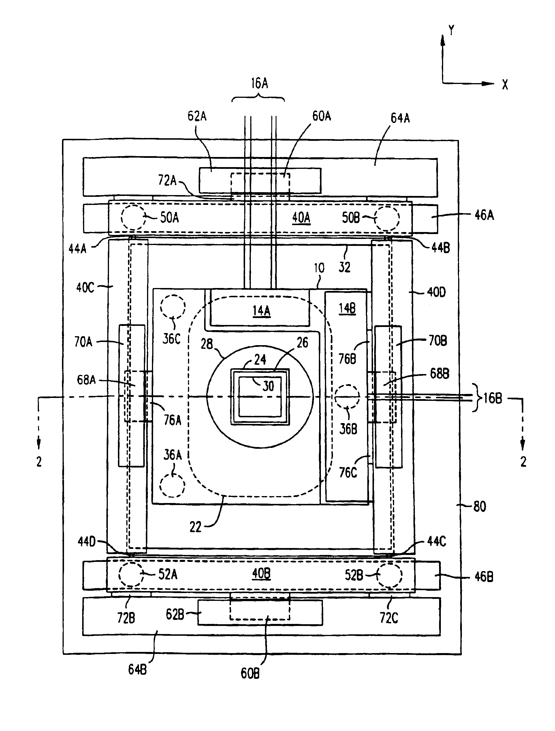
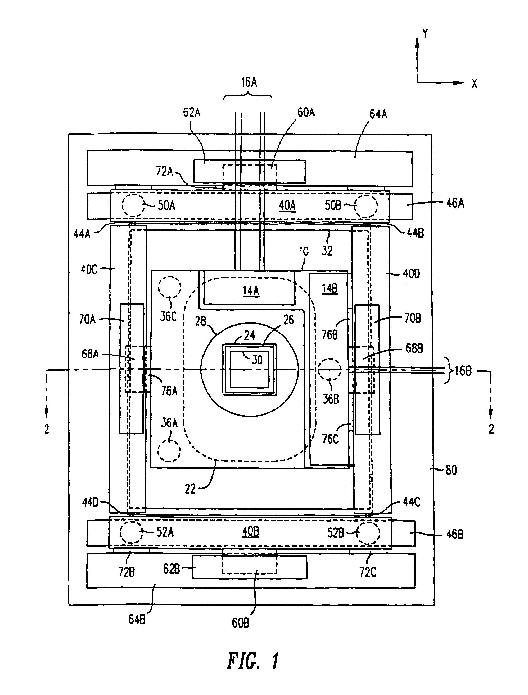
[0037]FIG. 1 shows a top view of a stage mechanism in accordance with the invention. See also copending commonly owned and invented U.S. patent application Ser. No. 08 / 221,375 entitled “Guideless Stage with Isolated Reaction Stage” filed Apr. 1, 1994, which is incorporated herein by reference and shows a related method of supporting elements of a stage mechanism so as to isolate reaction forces from the projection lens and other parts of a photolithography apparatus.

[0038]The detailed description from U.S. patent application Ser. No. 08 / 221,375 is reproduced below. FIGS. 1-11 of that application have been renumbered respectively as FIGS. 7-17, and the reference numerals have been increased by 200 in order to avoid the use of duplicate reference numerals for different elements.

The Detailed Description from U.S. patent application Ser. No. 08 / 221,375

[0039]While it will be appreciated by those skilled in the art that the guideless stage, with or without its isolating reaction frame, ha...


PUM

PropertyMeasurementUnit
sizeaaaaaaaaaa
thickaaaaaaaaaa
gravityaaaaaaaaaa

Abstract

A mask having a mask pattern is provided on a mask table. A substrate is provided on a substrate table. The mask is irradiated to project an image of at least a portion of the mask pattern onto a radiation-sensitive layer of the substrate using a projection system. At least one of the mask and substrate tables is positioned using a drive unit having a stationary part coupled to a reaction frame. A position of at least one of the mask and substrate tables is measured using a measuring system having a plurality of measurement sensors that have a stationary part and a movable part. The movable part of one of the sensors is coupled to the one of the mask table and the substrate table whose position is measured, and the stationary parts of the sensors are coupled to a support frame mechanically isolated from the reaction frame.

Description

[0001]This is a Division of application Ser. No. 09 / 449,762 filed Nov. 26, 1999, which in turn is a Continuation of application Ser. No. 09 / 192,153 filed Nov. 12, 1998 (now U.S. Pat. No. 6,246,202), which is a Continuation of application Ser. No. 08 / 416,558 filed Apr. 4,1995 (now U.S. Pat. No. 5,874,820). Said application Ser. No. 09 / 449,762 also is a Continuation-In-Part of application Ser. No. 09 / 127,288 filed Jul. 31, 1998 (now U.S. Pat. No. 6,049,186), which is a Continuation of application Ser. No. 08 / 627,824 filed Apr. 2, 1996 (now U.S. Pat. No. 5,942,871), which is a Continuation of application Ser. No. 08 / 221,375 filed Apr. 1, 1994 (now U.S. Pat. No. 5,528,118). The entire disclosures of the above-identified prior applications are hereby incorporated by reference herein in their entireties.BACKGROUND OF THE INVENTION[0002]1. Field of the Invention[0003]This invention relates to precision motion stages and more specifically to a stage suitable for use in a photolithography ma...

Claims


Application Information

Patent Timeline
Patent Type & Authority Patents(United States)
IPC IPC(8): G03F7/20H01L21/67H01L21/68
CPCG03F7/70358G03F7/70716G03F7/70833G03F7/709H01L21/68H01L21/682
Inventor LEE, MARTIN E.
Owner NIKON CORP
Why Eureka
Try Eureka