Visual display screen arrangement

Inactive Publication Date: 2005-08-09
SEAMLESS DISPLAY
View PDF21 Cites 156 Cited by
  • Summary
  • Abstract
  • Description
  • Claims
  • Application Information

AI Technical Summary

Benefits of technology

[0009]It is an object of the present invention to address these problems wish the prior art. Specifically, it is an object of the present inv

Problems solved by technology

Thus, when two or more such known displays are placed adjacent to one another, a visible gap occurs.
Such a gap is unaccep

Method used


Image

  • Visual display screen arrangement
  • Visual display screen arrangement
  • Visual display screen arrangement

Examples


Embodiment Construction

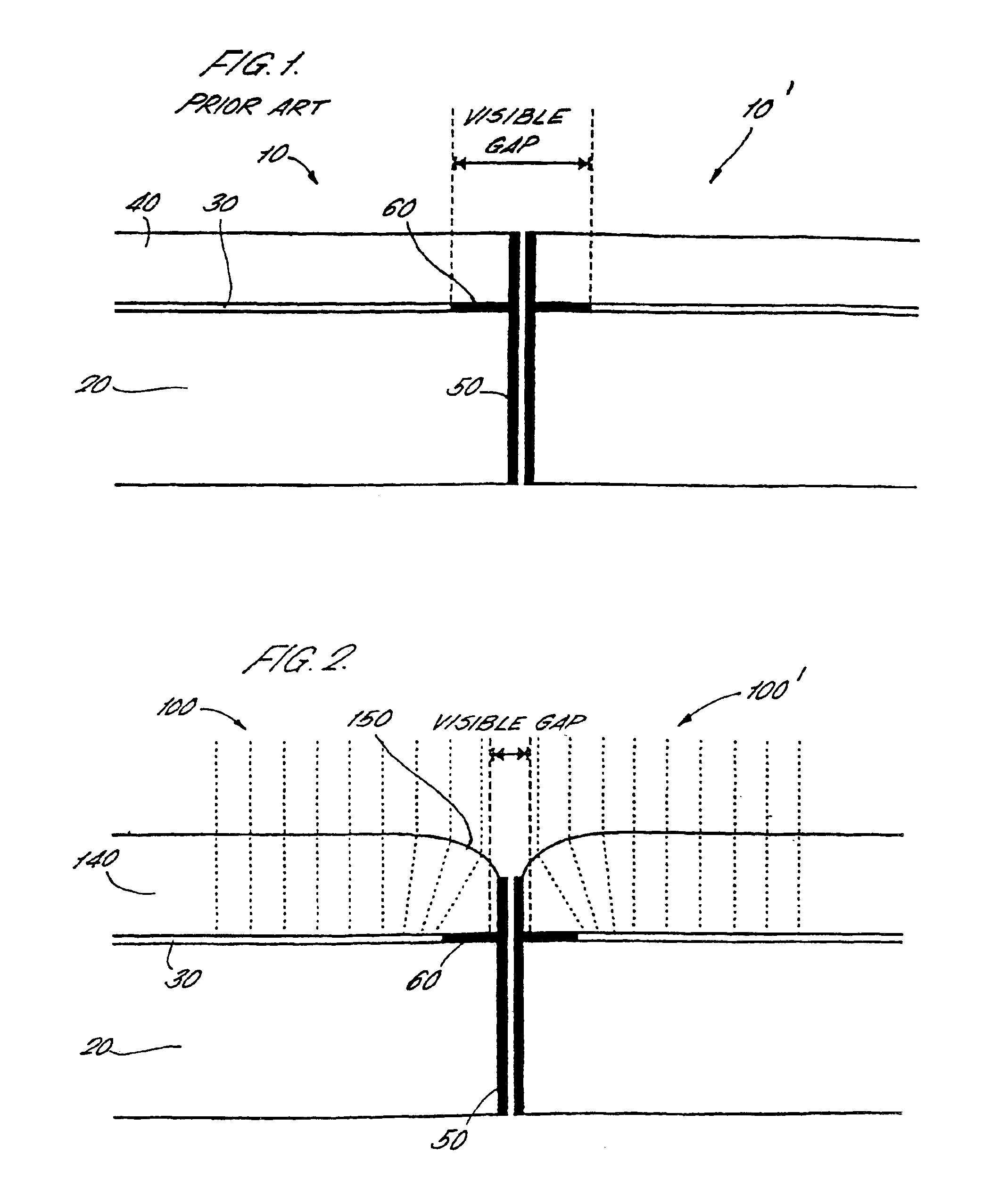
[0044]Referring first to FIG. 1, a highly schematic sectional view through the edge of two prior art liquid crystal display panels 10, 10′ is shown, roughly to scale. Each LCD panel comprises a supporting substrate 20 (typically including a reflector, first glass plate, first polarizing element and backlight where appropriate) onto which is mounted a glass cover plate 40. Sandwiched between the supporting substrate 20 and the glass cover plate 40 is a volume which forms an active display region 30. The active display region 30 contains a plurality of electrodes, as will be familiar to those skilled in the art, together with liquid crystals.

[0045]The panels 10, 10′ may be bounded by side walls 50 which provide mechanical protection to the panel. The liquid crystals are contained within the active display region 30 also by an epoxy edge seal which typically has a protective layer thereon. In consequence of this, there is a region adjacent to the edge of the LCD panel which cannot be u...


PUM


Abstract

A visual display screen (100′) such as an LCD screen is provided with a display area (30) for displaying an image. The display area (30) extends as far as an optically inactive region (60), containing device drivers, at the edge of the screen.
A cover plate assembly (40) overlays the display area (30). The cover plate assembly is laminar and an upper translucent plastics layer (520) thereof is planar over the display area (30) but is curved at the edge to provide a lens there. Thus, the image in the display area viewed through the cover plate assembly (40) appears to be shifted to the edge of the screen (100′) so that the optically inactive region (60) becomes invisible. Two screens can be abutted adjacent each other with no visible join using this technique. Compression of the image at the edge compensates for edge distortion by the lens. Repeating of the image either side of the join between two screens increases the viewing angle beyond which the join appears.

Description

CROSS-REFERENCE TO RELATED APPLICATION[0001]This Application is a Section 371 National Stage Application of International Application No. PCT / GB01 / 04926, filed Nov. 7, 2001 and published as WO 02 / 42838 on May 30, 2002.FIELD OF THE INVENTION[0002]This invention relates to a visual display screen arrangement.BACKGROUND OF THE INVENTION[0003]Many modern electrical or electronic devices contain a visual display. For example, mobile telephones, porkable and particularly palm-held digital computers each contain a (typically) backlit liquid crystal display (LCD) screen. In each case, the desire to miniaturise and thus increase the portability of such devices is balanced by the need to ensure that the screen that imparts information to the user has an adequate viewing area. In the field of mobile telephones, the emergence of technologies to view Internet pages has provided a further need to increase screen size.[0004]Although a screen can be provided which is physically larger than the devi...

Claims


Application Information

Patent Timeline
IPC IPC(8): G02F1/13G02F1/1335G02F1/1333G06F1/16G09F9/35G02F1/133G02B5/30G09F9/40
CPCG02F1/13336G02F1/133526G06F1/1616G06F1/1641G06F1/1643G09F9/35G02F1/13
Inventor STARK, BERNARD HARRY
Owner SEAMLESS DISPLAY
Why Eureka
Try Eureka