Blower with dual tubes

a technology of blowout tube and blower, which is applied in the direction of cleaning process and apparatus, cleaning using liquids, suction cleaners, etc., can solve the problems of not having two blowout tubes, patents that do not have two outlets, and the blowout tube has the least weight possible, so as to achieve the effect of less tim

Inactive Publication Date: 2005-08-16
ERICSON WILLIAM A
View PDF13 Cites 45 Cited by
  • Summary
  • Abstract
  • Description
  • Claims
  • Application Information

AI Technical Summary

Benefits of technology

[0019]It is another object of the present invention to provide a new and improved blower with dual tubes that may be easily and efficiently manufactured and marketed.
[0020]An even further object of the present invention is to provide a new and improved blower with dual tubes that has a low cost of manufacture with regard to both materials and labor, and which accordingly is then susceptible of low prices of sale to the consuming public, thereby making such blower with dual tubes economically available to the buying public.
[0022]Even still another object of the present invention is to provide a blower with dual tubes for directing debris to a precise location. This allows collection and removal of debris in less time.
[0023]Still yet another object of the present invention is to provide a blower with dual tubes for directing debris to a precise location. This makes it possible to direct debris with minimal movement of an operator carrying a blower.
[0024]Still yet another object of the present invention is to provide a blower with dual tubes for directing debris to a precise location. This makes it possible to position each tube independently of the other.

Problems solved by technology

Of necessity, blowers have the least weight possible and occupy a small volume.
However, the Honda '415 patent does not have two outlets, and has further drawbacks of no elbow and no separate tube.
However, the Gamoh '778 patent does not have two outlets, and additionally does not have a pivoting tube.
However, the Yamami '208 patent does not have two blowout tubes.
However, the Sapp '058 patent does not have dual tubes and cannot rotate and pivot elbows about an air outlet.
However, the Griffin '274 patent does not have dual outlets and elbows to direct the airflow.
However, the Hesskamp '305 patent does not have tubes extending substantially outward from the housing, and has the additional deficiencies of no backpack mounting and a separate power source.
While the above-described devices fulfill their respective, particular objectives and requirements, the aforementioned patents do not describe a blower with dual tubes that allows directing debris to a precise location.

Method used


Image

  • Blower with dual tubes
  • Blower with dual tubes
  • Blower with dual tubes

Examples


Embodiment Construction

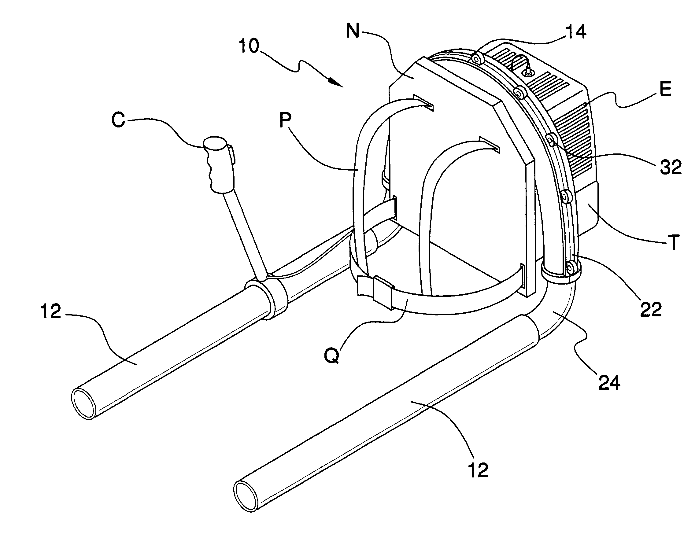
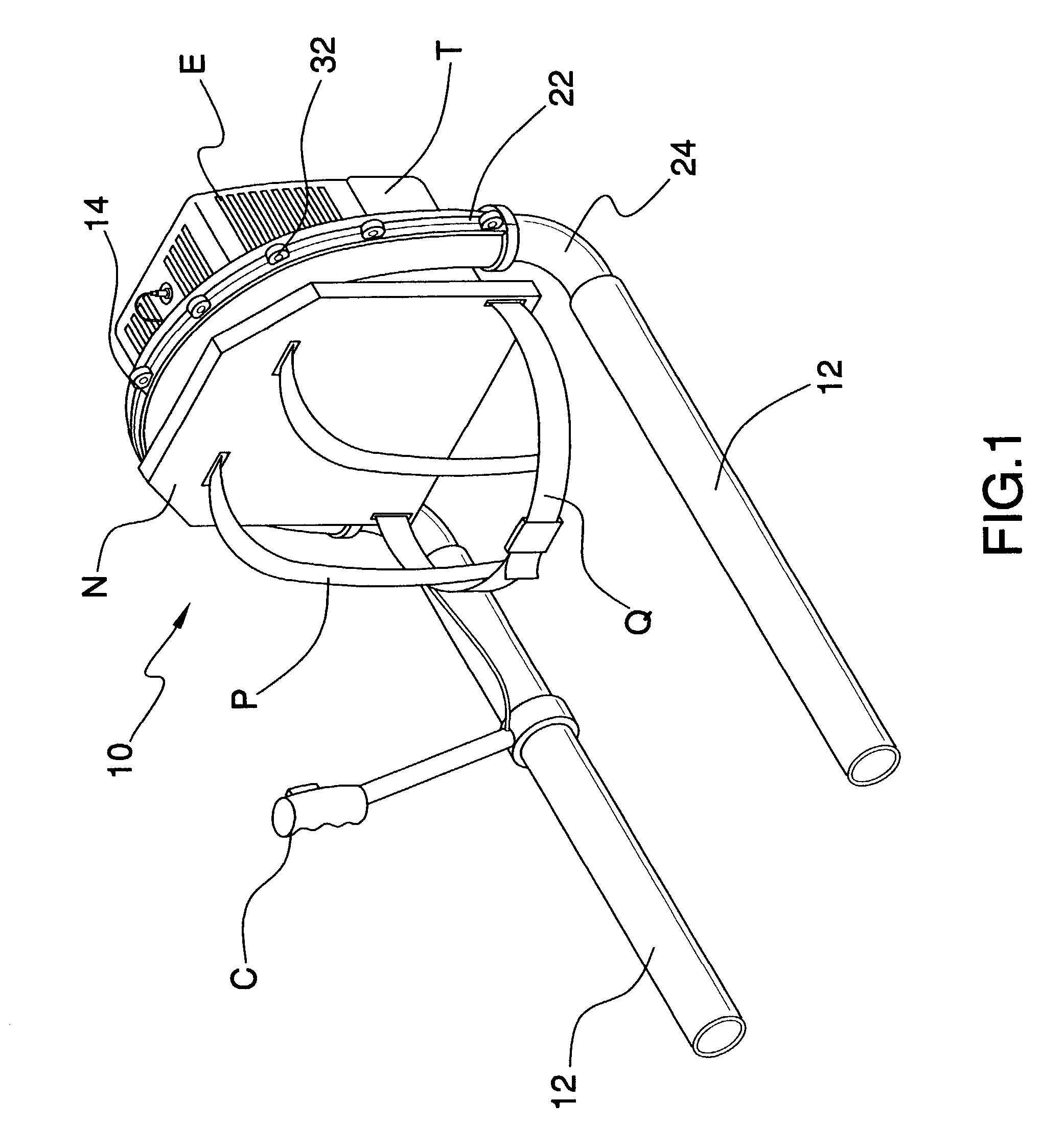
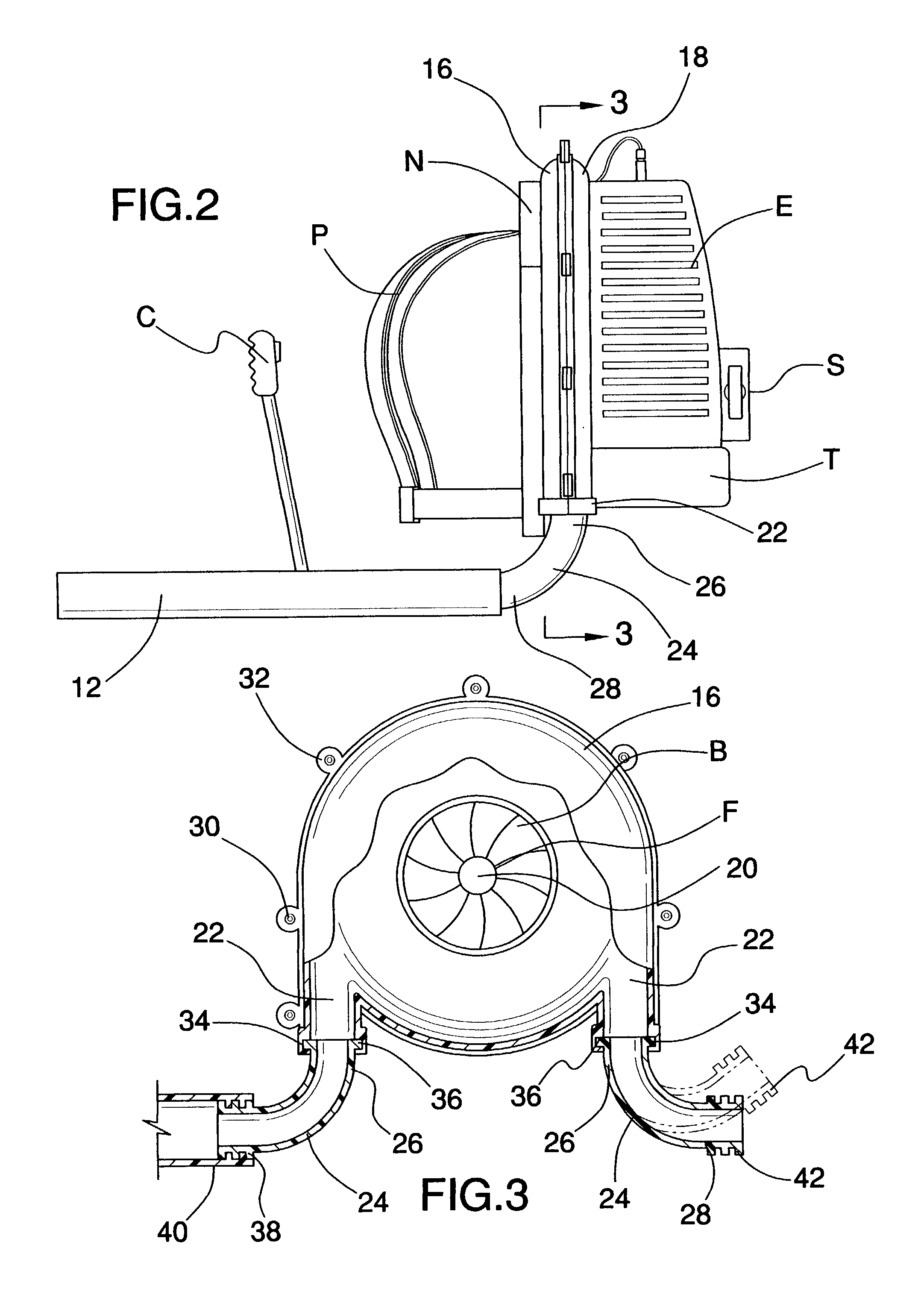
[0033]Referring now to the drawings, and particularly to FIGS. 1–4, a preferred embodiment of the blower with dual tubes of the present invention is shown and generally designated by the reference numeral 10.

[0034]In FIG. 1, a new and improved blower 10 with dual tubes 12 of the present invention for directing debris to a precise location is illustrated and will be described. An operator generally carries the blower 10 with dual tubes 12 upon the operator's back with straps P, a belt Q, and a frame N. More particularly, the blower 10 with dual tubes 12 has a conventional design comprising an engine E, a starter S, a fuel tank T, a fan F powered by the engine E, a frame N supporting the engine E, and a control mechanism C. Two hollow tubes 12 connected to two outlets 22 upon the housing 14 improve upon the conventional design. The engine E is a typical two-cycle internal combustion engine E provided with fuel from the fuel tank T. An operator starts the blower 10 with dual tubes 12 b...


PUM


Abstract

A backpack blower has a lightweight engine, a starter, a fuel tank, a fan, a frame for the engine, two hollow tubes, and a control mechanism upon one tube. The blower improvement comes from a housing and two elbows. The round housing contains the fan and has two tangential outlets. The two elbows have a generally round cross section and a generally right angle shape. On each elbow, the first end connects with an outlet and the second end joins a tube. The elbows rotate and bend, directing leaves and debris with airflow from the tubes.

Description

BACKGROUND OF THE INVENTION[0001]1. Field of the Invention[0002]The present invention relates to a blower with dual tubes for use in connection with dispersing debris from lawns, driveways, or other grounds. The blower with dual tubes has particular utility in connection with directing debris to a precise location.[0003]2. Description of the Prior Art[0004]Blowers with dual tubes are desirable for commercial lawn companies and homeowners. Blowers typically disperse or collect debris usually lawn clippings and leaves. A typical blower has a fan that rotates in a plane generally perpendicular to the ground. The fan directs airflow from a housing through an outlet and into a single tube. Blowers often mount to a backpack frame carried by an operator. Of necessity, blowers have the least weight possible and occupy a small volume. The backpack frame has straps and a belt for removably supporting a blower upon an operator.[0005]In spring and summer, blowers disperse lawn clippings and deb...

Claims


Application Information

Patent Timeline
Patent Type & Authority Patents(United States)
IPC IPC(8): A47L5/12A47L5/14A01G1/12
CPCA01G1/125A47L5/14A01G20/47
Inventor ERICSON, WILLIAM A.
Owner ERICSON WILLIAM A
Why Eureka
Try Eureka