Gas turbine combustor and operating method thereof

a technology of gas turbines and combustor blades, which is applied in the ignition of turbine/propulsion engines, engine starters, lighting and heating apparatus, etc., can solve the problems of flame stabilization, high level nox emission of diffused combustion systems, and combustion stability of premixed combustion systems, etc., to achieve good combustion stability and operation methods, the effect of low level nox emission

Inactive Publication Date: 2005-08-16
MITSUBISHI HITACHIPOWER SYST LTD
View PDF9 Cites 55 Cited by
  • Summary
  • Abstract
  • Description
  • Claims
  • Application Information

AI Technical Summary

Benefits of technology

[0008]The main purpose of the present invention is to provide a gas turbine combustor having low level NOx emission and good combustion stability and an operating method thereof.

Problems solved by technology

In said prior art technology, a diffusion combustion system has a problem of high level NOx.
A premixed combustion system also has problems of combustion stability, such as flash back, and flame stabilization during the startup operation and partial loading operation.

Method used


Image

  • Gas turbine combustor and operating method thereof
  • Gas turbine combustor and operating method thereof
  • Gas turbine combustor and operating method thereof

Examples


first embodiment

[0046

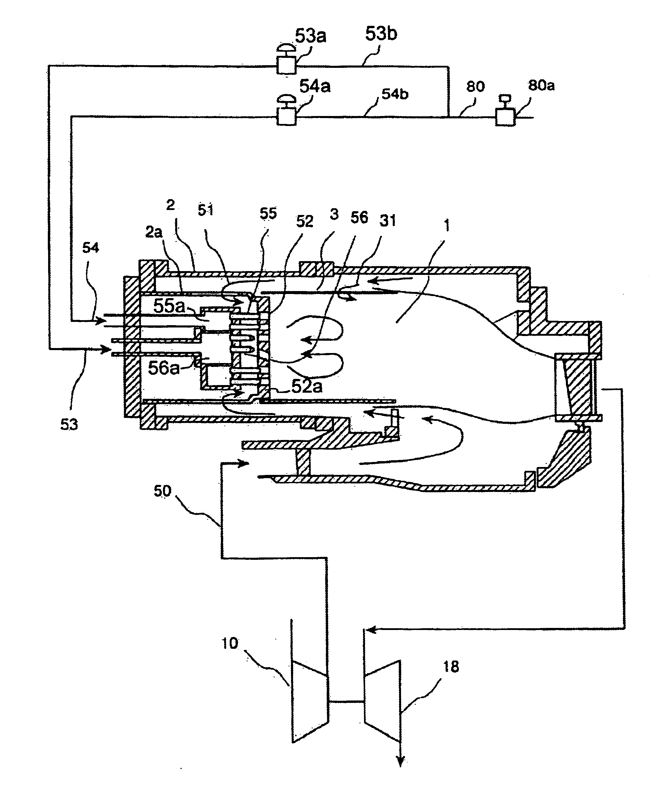
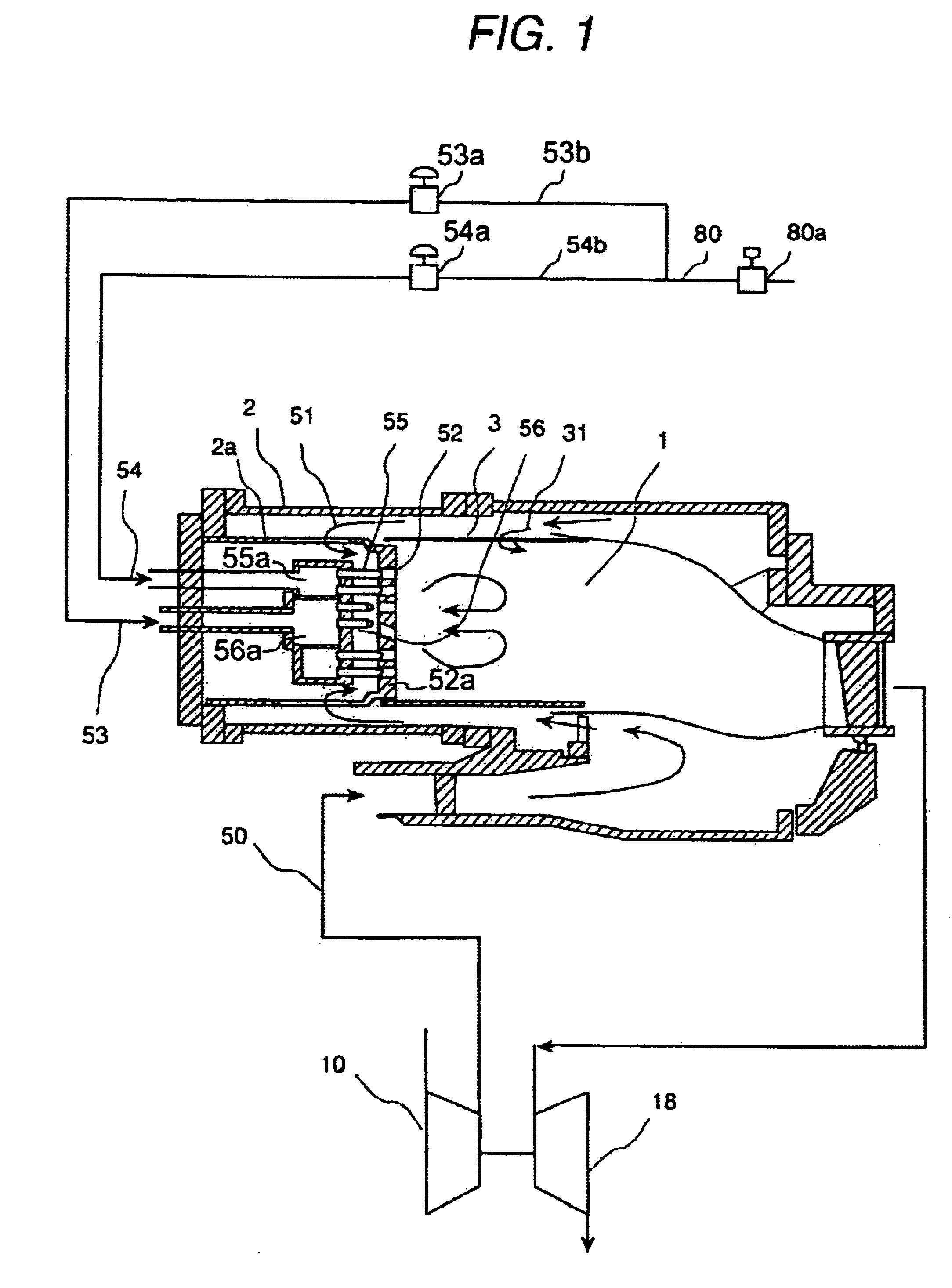
[0047]A first embodiment according to the present invention will be described hereunder with reference to FIG. 1. In FIG. 1, air 50 sent from a compressor 10 passes between an outer casing 2 and a combustor liner 3. A portion of the air 50 is blown into a combustion chamber 1 as cooling air 31 for the combustor liner 3. Further, remaining air 50 is blown into the combustion chamber 1 as coaxial air 51 from the interior of inner cylinder 2a through air holes 52 in an inner end wall 52a of the inner cylinder. End wall 52a is in the form of a disc member.

[0048]Fuel nozzles 55 and 56 are disposed coaxially or almost coaxially with combustion air holes 52. Fuel 53 and fuel 54 are injected into a combustion chamber 1 from fuel nozzles 55 and fuel nozzles 56 through supply paths 55a, 56a as jets almost coaxial with the combustion air thereby forming a stable flame. Generated high-temperature combustion gas is sent to a turbine 18, performs its work, and then is exhausted.

[0049]In this...

second embodiment

[0062

[0063]FIGS. 5(a) and 5(b) show the detail of the nozzle portion of a second embodiment. In this embodiment, there is a single fuel system which is not partitioned into a central portion and a surrounding portion. Further, a swirling angle is not given to the nozzles in the central portion and the combustion air holes. This embodiment allows the nozzle structure to be simplified in cases where the combustion stability does not matter much according to operational reason or the shape of the fuel.

third embodiment

[0064

[0065]FIGS. 6(a) and 6(b) show a third embodiment. This embodiment is arranged such that a plurality of nozzles of a second embodiment shown in FIG. 5 are combined to form a single combustor. That is, a plurality of modules, each consisting of fuel nozzles and air holes, are combined to form a single combustor.

[0066]As described in a first embodiment, such an arrangement can provide a plurality of fuel systems so as to flexibly cope with changes of turbine loads and also can easily provide different capacity per one combustor by increasing or decreasing the number of nozzles.


PUM


Abstract

A gas turbine combustor has a combustion chamber into which fuel and air are supplied, wherein the fuel and the air are supplied into said combustion chamber as a plurality of coaxial jets.

Description

[0001]This is a continuation-in-part (CIP) application of U.S. Ser. No. 10 / 083,360 filed Feb. 27, 2002, now pending, the entire disclosure of which is hereby incorporated by reference.BACKGROUND OF THE INVENTION[0002]1. Field of the Invention[0003]The present invention relates to a gas turbine combustor and an operating method thereof.[0004]2. Description of Prior Art[0005]The present invention specifically relates to a low NOx type gas turbine combustor which emits low levels of nitrogen oxides. The prior art has been disclosed in Japanese Application Patent Laid-Open Publication No. Hei 05-172331.[0006]In a gas turbine combustor, since the turndown ratio from startup to the rated load condition is large, a diffusion combustion system which directly injects fuel into a combustion chamber has been widely employed so as to ensure combustion stability in a wide area. Also, a premixed combustion system has been made available.[0007]In said prior art technology, a diffusion combustion s...

Claims


Application Information

Patent Timeline
Patent Type & Authority Patents(United States)
IPC IPC(8): F23R3/36F23R3/10F23R3/28F23R3/04F02C7/22F02C7/232
CPCF02C7/22F02C7/232F23R3/10F23R3/28F23R3/286F23R3/36F23R2900/03282
Inventor INOUE, HIROSHIKOGANEZAWA, TOMOMIKOBAYASHI, NARIYOSHITAKEHARA, ISAO
Owner MITSUBISHI HITACHIPOWER SYST LTD
Why Eureka
Try Eureka