Device for removing a broken light bulb from a socket

a technology for removing a broken light bulb and a socket, which is applied in the direction of wrenches, screwdrivers, electric discharge tubes/lamp manufacture, etc., can solve the problems of difficult removal, inconvenient removal, and seizing of the base of incandescent bulbs within the socket,

Inactive Publication Date: 2005-08-16
RAININ EDGAR A +1
View PDF12 Cites 10 Cited by
  • Summary
  • Abstract
  • Description
  • Claims
  • Application Information

AI Technical Summary

Benefits of technology

[0011]The device of the present invention is intended to be used manually by a person removing the base of a broken incandescent light bulb. The device of the present invention includes a member which is preferably elongated and terminates in an end having an outer surface which is capable of extending into the hollow base of the broken light bulb. The member may be formed of non-electrically conductive material such as plastic, wood, ceramic material and the like. The member may also take the form of a hollow tube such that the end extending into the hollow base of the broken light bulb accommodates remnants of a light bulb filament and stray glass. The remaining portion of the member includes a gripping surface for the user who is applying a torsional force to the member in its operation, which will be more fully discussed hereinafter. The member may also possess a certain degree of rigidity allowing the user to swing the same against the remaining filament and glass portions of the light bulb prior to removal of the base. In this manner, the end of the member is more easily inserted into the hollow base of the broken light bulb.
[0020]Yet another object of the present invention is to provide a device for removing a hollow base of a broken light bulb from a socket which may be employed with an extending element to eliminate the use of a ladder in removing such broken light bulb base from the socket.

Problems solved by technology

Over time, the bases of incandescent bulbs within sockets tend to seize up and are very difficult to remove when they expire.
Compounding the problem is the fact that the glass portion of the incandescent bulb often breaks when grasped and twisted, adding to the difficulty of removing the metallic base of the incandescent bulb from the metallic socket.
In addition, remnants of the incandescent bulb had been removed with the pliers which caused damage to eyes of a person removing the bulb.
Moreover, if the person removing the bulb forgets to turn off the electrical current to the lamp, the person removing the bulb may receive an electric shock through the metallic pliers.

Method used


Image

  • Device for removing a broken light bulb from a socket
  • Device for removing a broken light bulb from a socket
  • Device for removing a broken light bulb from a socket

Examples


Embodiment Construction

[0028]Various aspects of the present invention are revealed from the following detailed description of the preferred embodiments and should be referenced to the prior delineated drawings.

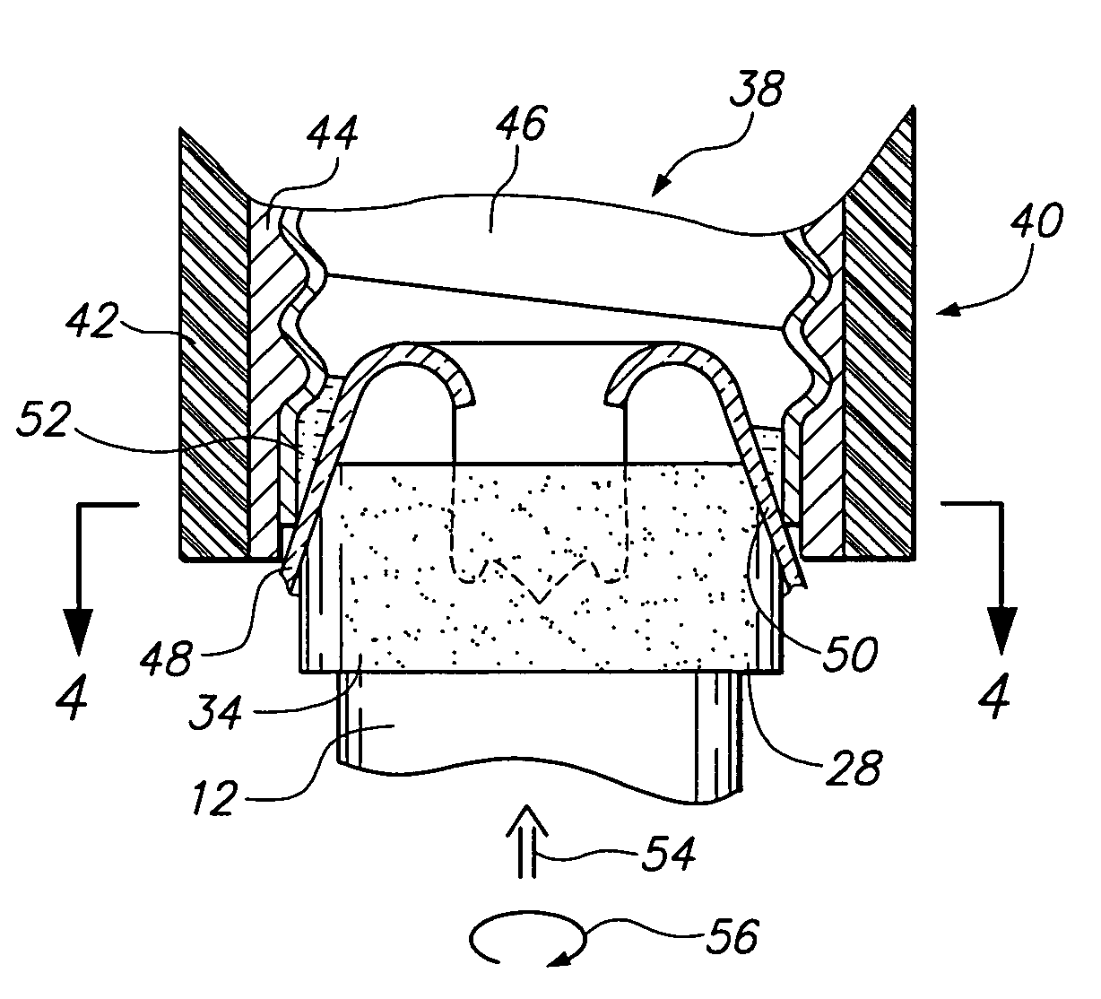
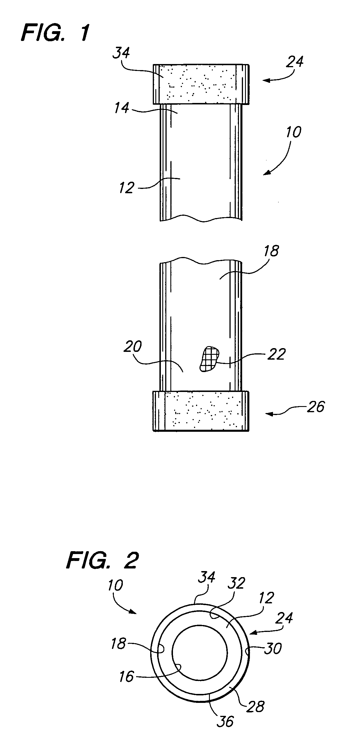
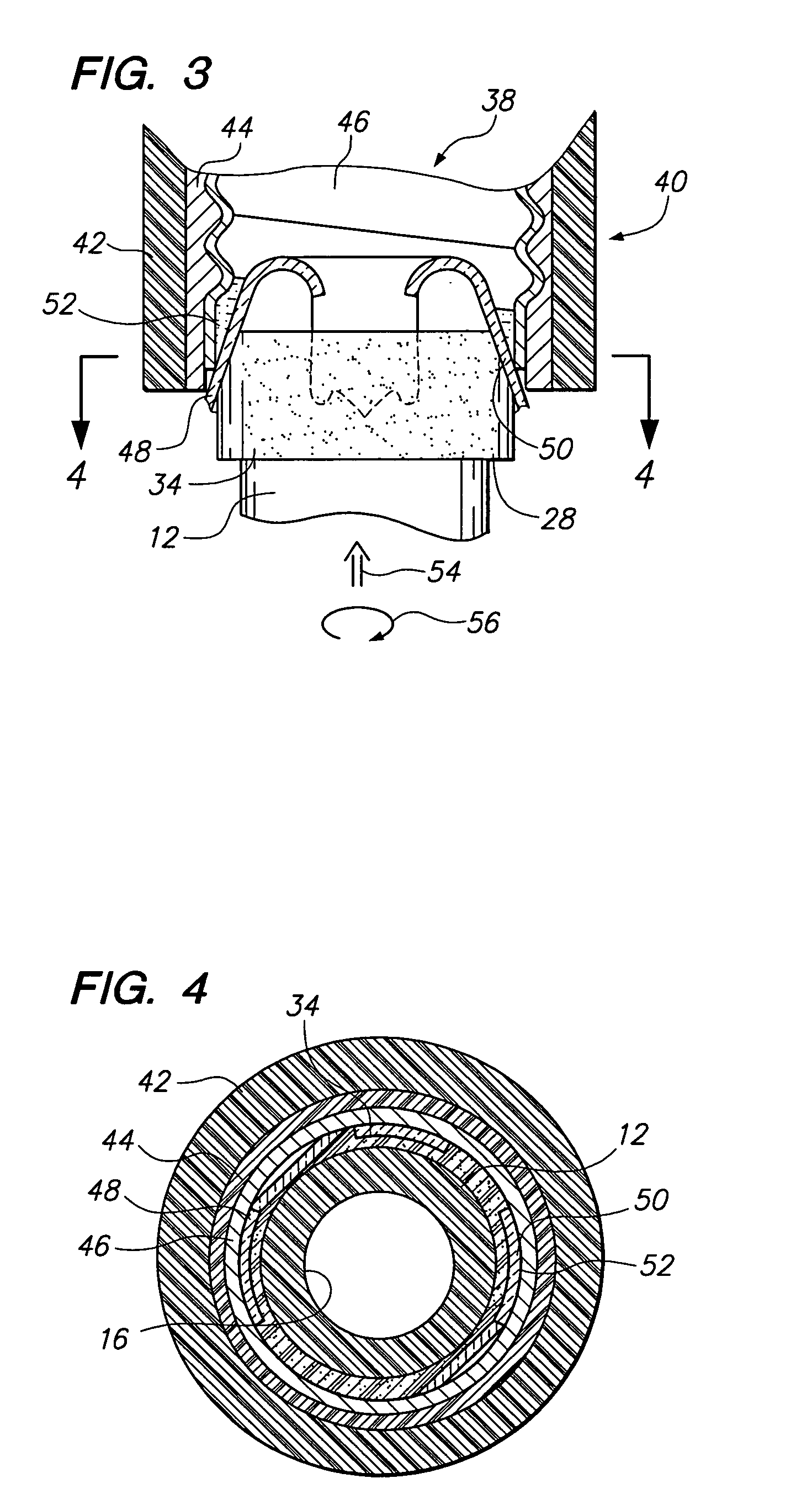
[0029]The embodiment of the invention as a whole is depicted in the drawings by reference character 10, FIGS. 1 and 2. Device 10 includes as one of its elements an elongated member 12 which may take the form of a hollow cylindrical tube formed of a non-electrically conductive material such as polyvinyl chloride. Member 12 is formed with an end portion 14 possessing a diameter or transverse dimension which is compatible with the use of device 10, which will be described in greater detail hereinafter. With reference to FIG. 2, it may be observed that member 12 includes an inner surface 16 and an outer surface 18. With reference again to FIG. 1, it should be seen that member 12 further includes an end portion 20. It is intended that end portion 20 be gripped by the user of device 10. In this regard, kn...


PUM


Abstract

A device for removing a hollow base of a broken light bulb utilizing a member terminating in an end surface which is capable of extending into the hollow base of a bulb. The member also includes a portion capable of receiving an applied torsional force. An adhesive band is fixed to the outer surface of the member. The adhesive band bonds with the hollow base of the broken light bulb to permit removal of the same via the torsional force.

Description

CROSS-REFERENCES TO RELATED APPLICATIONS[0001]The present application is related to and claims the benefit of Provisional Patent Application 60 / 524,493, filed 21 Nov. 2003 and 60 / 525,709, filed 28 Nov. 2003.BACKGROUND OF THE INVENTION[0002]The present invention relates to a novel and useful device for removing a hollow base of a broken light bulb.[0003]Incandescent light bulbs normally are constructed with a threaded metallic base portion that is threaded or screwed into a socket having a corresponding threaded portion. Over time, the bases of incandescent bulbs within sockets tend to seize up and are very difficult to remove when they expire. Compounding the problem is the fact that the glass portion of the incandescent bulb often breaks when grasped and twisted, adding to the difficulty of removing the metallic base of the incandescent bulb from the metallic socket.[0004]In the past, removal of such bulbs required one or two pairs of pliers to grab the metallic base of the incande...

Claims


Application Information

Patent Timeline
Patent Type & Authority Patents(United States)
IPC IPC(8): B25B13/00B25B13/48B25B27/14B25B27/18H01J9/00H01K3/32
CPCB25B13/48B25B27/18H01J9/003H01K3/32
Inventor RAININ, EDGAR A.RAININ, JUDITH W.
Owner RAININ EDGAR A
Why Eureka
Try Eureka