Air powered wrench device with pivotable head and method of using

a technology of pivoting head and wrench, which is applied in the direction of wrenches, power driven tools, screwdrivers, etc., can solve the problems of increasing the complexity and weight of the wrench, the shaft is susceptible to fatigue, and the straight fixed head of the wrench is difficult to use, etc., to achieve easy and efficient manufacturing and marketing, and low manufacturing cost. , the effect of low price of sal

Inactive Publication Date: 2005-08-16
EYSSALLENNE LUIS P
View PDF5 Cites 776 Cited by
  • Summary
  • Abstract
  • Description
  • Claims
  • Application Information

AI Technical Summary

Benefits of technology

[0015]It is another object of the present invention to provide a new and improved wrench device that may be easily and efficiently manufactured and marketed.
[0016]An even further object of the present invention is to provide a new and improved wrench device that has a low cost of manufacture with regard to both materials and labor, and which accordingly is then susceptible of low prices of sale to the consuming public, thereby making such multipurpose storage unit and system economically available to the buying public.

Problems solved by technology

Wrenches having a straight fixed head are difficult to use in tight spaces which are often readily accessible by wrenches having a head located at an angled position relative to a body of the wrench.
This is inconvenient since it generally requires two hands to adjust the head and requires the wrench to be moved away from the fastener the wrench is being used to loosen or tighten.
A separate but related problem, particularly associated with power wrenches is the transmission of power through a pivot point.
Since the shaft is subject to constant bending, the shaft is susceptible to fatigue over a period of time.
Thus the wrench has several different parts required for pivoting, adding to the complexity and weight of the wrench.

Method used


Image

  • Air powered wrench device with pivotable head and method of using
  • Air powered wrench device with pivotable head and method of using
  • Air powered wrench device with pivotable head and method of using

Examples


Embodiment Construction

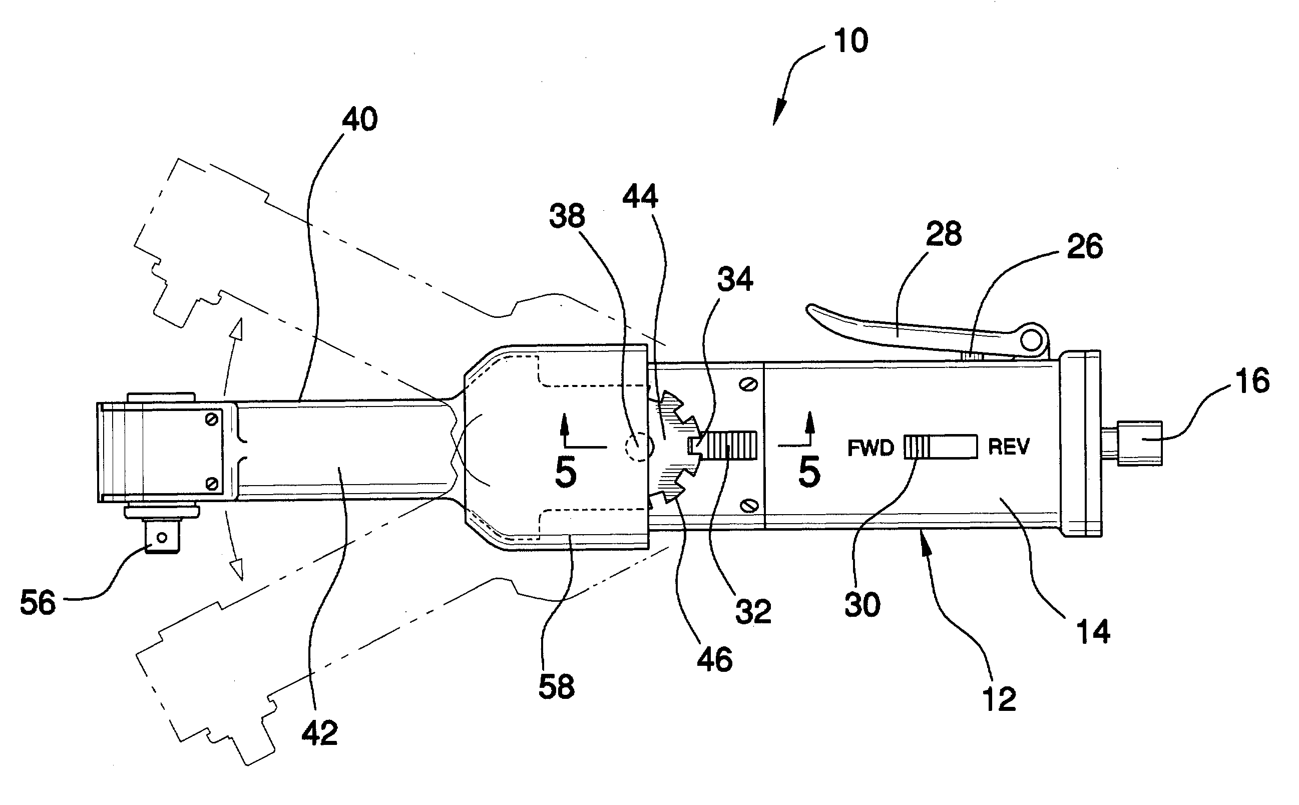
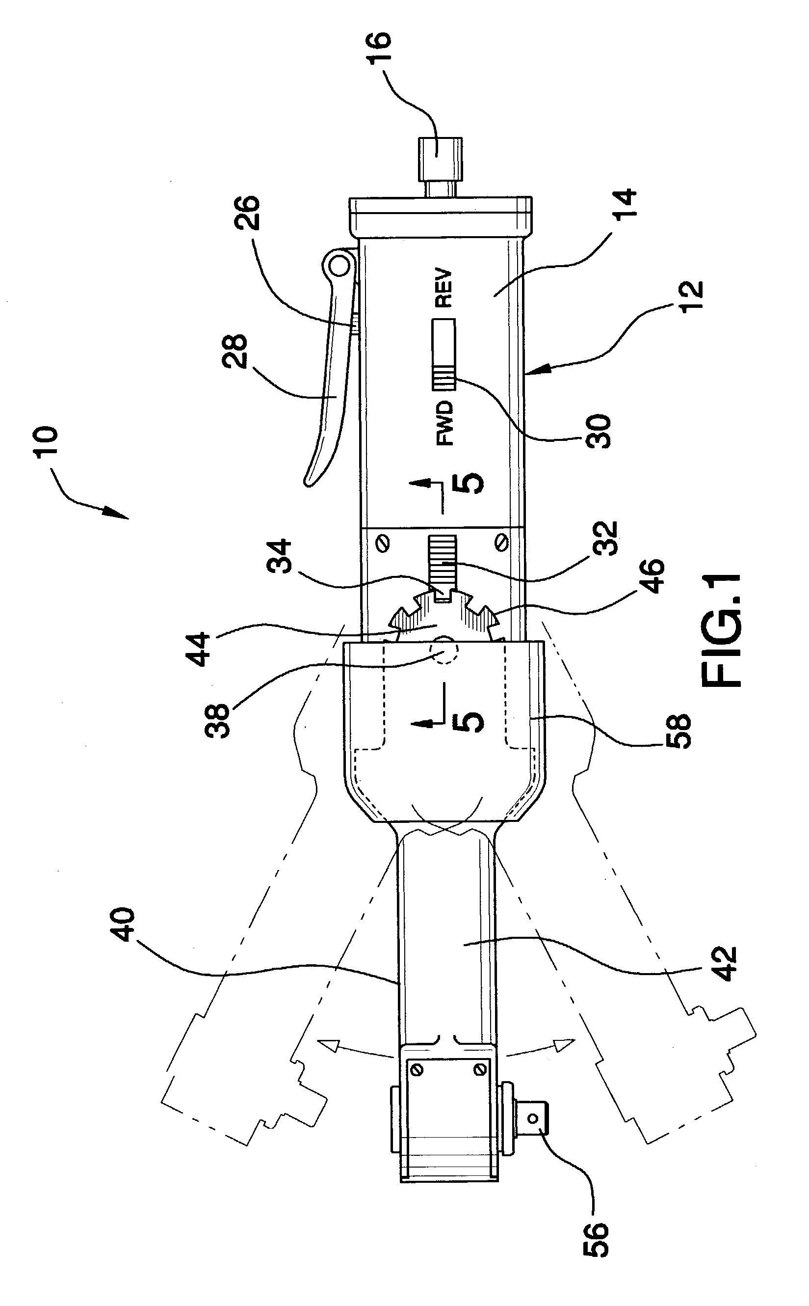
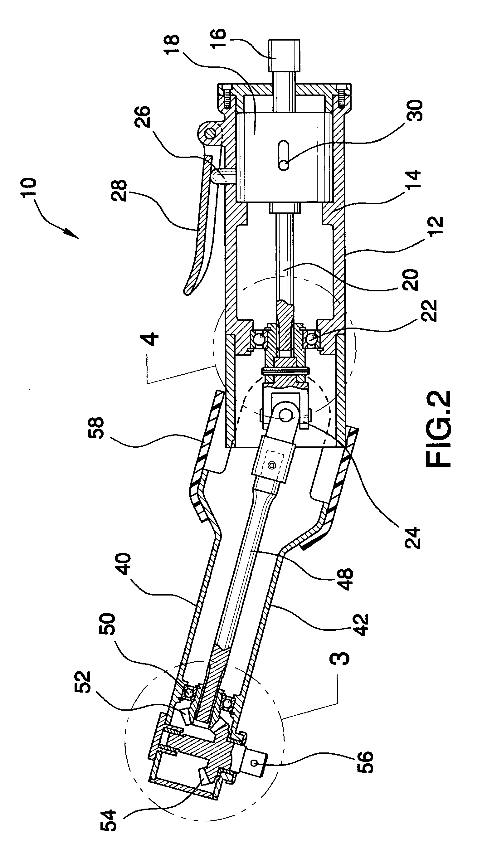
[0029]Referring now to the drawings, and in particular FIGS. 1 to 5 thereof, one preferred embodiment of the present invention is shown and generally designated by the reference numeral 10. One preferred embodiment of an air wrench device 10 comprises a handle 12 pivotally attached to an arm 40. The handle 12 includes: a housing 14, an air intake nozzle 16, an air driven motor 18, a drive shaft 20, a ball bearing collar 22, a universal joint 24, an on / off button 26, a trigger switch 28, a directional throw switch 30, a lock pin 32, a spring 36, and a pivot post 38. The an air intake nozzle 16 is attached to the housing 14, the housing 14 having a distal end and a proximate end. The air driven motor 18 is attached to the proximate end of the housing 14, in which the air driven motor 18 is operatively attached to the air intake nozzle 16. The drive shaft 20 is operatively attached to the air driven motor 18. The ball bearing collar 22 is attached to the proximate end of the housing 14...


PUM


Abstract

An air powered wrench device with a pivotable head and associated method of using. The device comprises a handle pivotally attached to an arm. The handle comprises a housing, an air intake nozzle, an air driven motor, a drive shaft, a ball bearing collar, a universal joint, an on/off button, a trigger switch, a directional throw switch, a lock pin, a spring, and a pivot post. The arm is pivotally attached to the handle via the pivot post. The arm includes: an outer casing, an extension rod, a ball bearing sleeve, a first pawl gear, a second pawl gear, and a bit connector. The method of using the device comprises the steps of adjoining, affixing, aligning, allowing, enshrouding, getting, moving, obtaining, putting, rotating, shifting, squeezing, and tightening.

Description

FIELD OF THE INVENTION[0001]The present invention relates hand tools, more particularly, to an air powered wrench device with a pivotable head and a associated method of using the device.DESCRIPTION OF THE PRIOR ART[0002]Wrenches having a straight fixed head are difficult to use in tight spaces which are often readily accessible by wrenches having a head located at an angled position relative to a body of the wrench. Many currently available wrenches that have an adjustable head typically require the head to be moved away from the body to adjust the position of the head relative to the body. This is inconvenient since it generally requires two hands to adjust the head and requires the wrench to be moved away from the fastener the wrench is being used to loosen or tighten.[0003]A separate but related problem, particularly associated with power wrenches is the transmission of power through a pivot point. A power wrench currently available with an adjustable head has a continuous flexi...

Claims


Application Information

Patent Timeline
Patent Type & Authority Patents(United States)
IPC IPC(8): B25B17/00B25B21/00B25B23/00B25F5/02
CPCB25B21/00B25F5/02
Inventor EYSSALLENNE, LUIS P.
Owner EYSSALLENNE LUIS P
Why Eureka
Try Eureka