Lighting fixture

a technology of light fixture and light fixture body, which is applied in the direction of lighting elements, lighting and heating apparatus, instruments, etc., can solve the problems of significant electromagnetic interference source, limited available space, and increased mounting and maintenance costs

Inactive Publication Date: 2005-08-16
TEKNOWARE
View PDF27 Cites 43 Cited by
  • Summary
  • Abstract
  • Description
  • Claims
  • Application Information

AI Technical Summary

Benefits of technology

[0006]It is an object of the present invention to provide a lighting fixture avoiding the above drawbacks and allowing implementation of a continuous light line in a simple manner so that the size of the lighting fixture is not bigger than that of current known lighting fixtures. The object is achieved with a lighting fixture according to the invention, characterized in that the lighting fixture further comprises one or more cover plates, which are arranged at the connecting devices between the globe part and the background part of the lighting fixture to substantially cover the connecting devices, and one or more second light sources, which are arranged in connection with the cover plate to provide lighting from the region between the successive elongated light sources.

Problems solved by technology

In this case, too, the available space is limited.
In addition, the wiring between the light sources and the connecting device must be led through the frame of the lighting fixture behind the actual lighting fixture, which increases mounting and maintenance expenses.
If the connecting device also has a high frequency, the required wiring can, be a significant electromagnetic interference source.
In this case, however, the lighting source becomes physically large and expensive, and such a big lighting fixture cannot be placed reasonably in the roof of a passenger cabin of a transport vehicle.

Method used


Image

  • Lighting fixture
  • Lighting fixture
  • Lighting fixture

Examples


Embodiment Construction

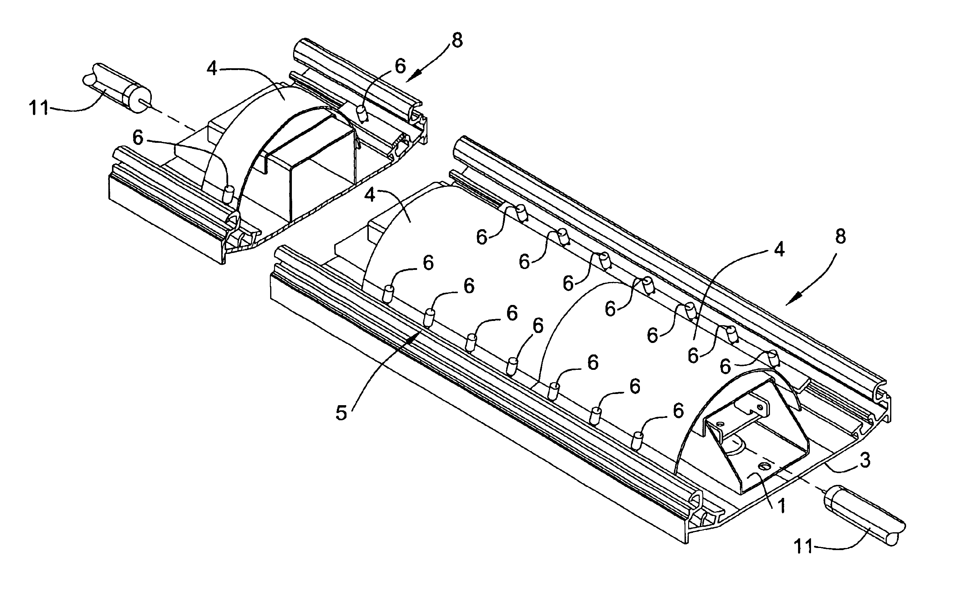
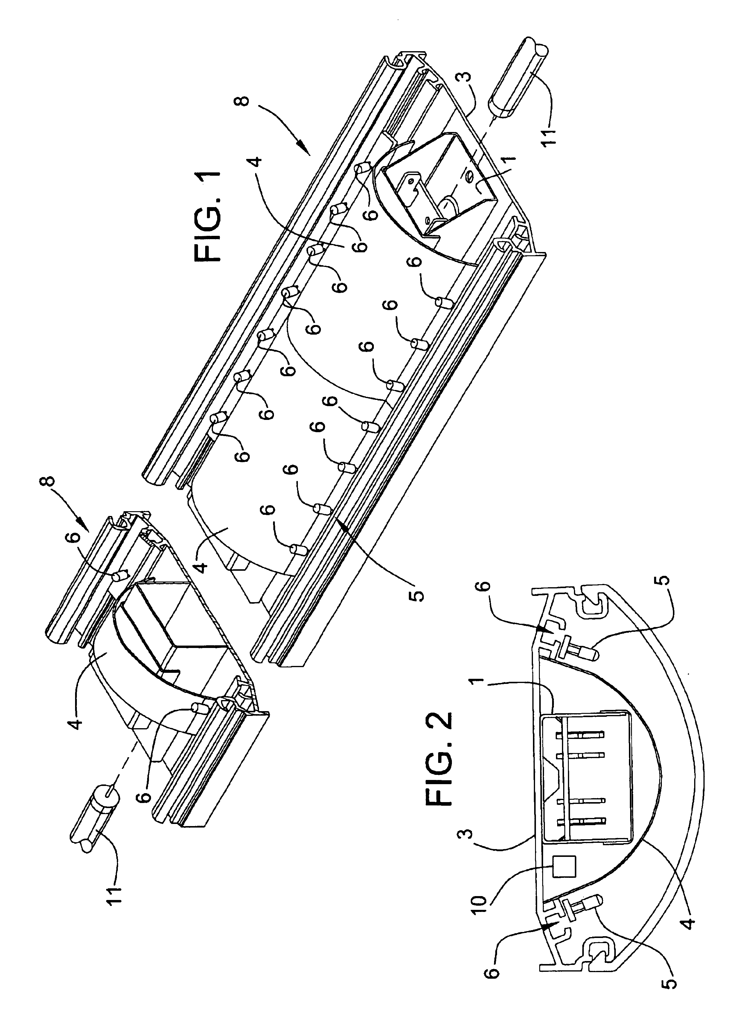
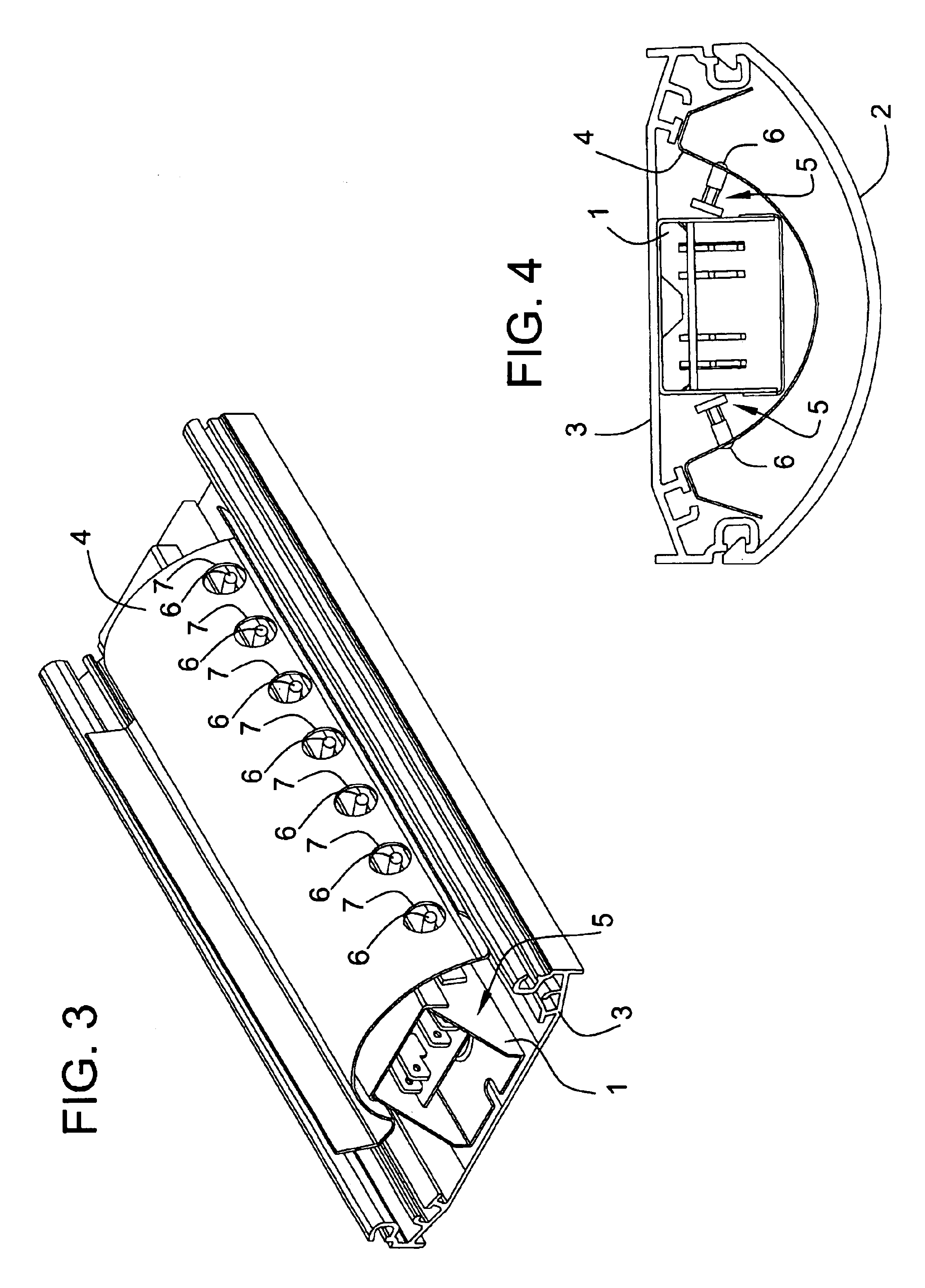
[0017]The lighting fixture of the invention, whose partial schematic structure according to an embodiment is shown in FIG. 1, is arranged to receive two or more elongated light sources positioned one after another. Elongated light sources are typically fluorescent lamps. The light sources are positioned one after another in the longitudinal direction to provide a long light line. The light line and the lighting fixture of the invention can be made as long as desired. The lighting fixture of the invention can thus have the length of a passenger cabin of a bus, for instance. The lighting fixture of the invention can also be implemented so that the lighting fixture comprises two parallel light sources. Compared with one lighting fixture, the luminous efficiency can thus be correspondingly increased.

[0018]The lighting fixture of the invention also comprises one or more connecting devices 1, which are arranged to supply energy to the light sources in order to burn them and positioned in ...


PUM


Abstract

A lighting fixture, which is arranged to receive two or more elongated light sources positioned one after another in the longitudinal direction of the light sources, the lighting fixture comprising one or more connecting devices, which are arranged to supply energy to the light sources in order to burn them and positioned in a region between the successive light sources in the lighting fixture, and a globe part and a background part, which are arranged to be connected to one another and to substantially surround the light sources and the connecting devices. The lighting fixture further comprises one or more cover plates, which are arranged at the connecting devices between the globe part and the background part of the lighting fixture to substantially cover the connecting devices, and one or more second light sources, which are arranged in connection with the cover plate to provide lighting from the region between the successive elongated light sources.

Description

BACKGROUND OF THE INVENTION[0001]The present invention relates to a lighting fixture, which is arranged to receive two or more elongated light sources positioned one after another in the longitudinal direction of the light sources, the lighting fixture comprising one or more connecting devices, which are arranged to supply energy to the light sources in order to burn them and positioned in a region between the successive light sources in the lighting fixture, and a globe part and a background part, which are arranged to be connected to one another and to substantially surround the light sources and the connecting devices.[0002]The interiors of public transport vehicles are typically illuminated by light lines, i.e. light fixtures with a length of the passenger cabin. The purpose of light lines is to provide an even lighting over the entire distance of the line so that the light line would not have shadows or significant deviations in the intensity of lighting it provides. Convention...

Claims


Application Information

Patent Timeline
Patent Type & Authority Patents(United States)
IPC IPC(8): B60Q3/02B60Q3/00F21S8/00F21S4/00F21V8/00F21S4/28F21Y103/10F21Y113/00F21Y115/10
CPCB60Q3/004B60Q3/0246B60Q3/025F21S4/008F21V23/06F21S8/04F21V2200/15F21Y2101/02F21Y2103/003F21Y2113/00F21S4/28F21Y2103/10F21Y2115/10B60Q3/64B60Q3/41B60Q3/43
Inventor KUISMA, JOUKO
Owner TEKNOWARE
Why Eureka
Try Eureka