Cutting insert and cutting insert holder therefor

a technology of cutting inserts and cutting inserts, which is applied in the field of cutting bits, can solve the problems of reducing the capacity and reducing the efficiency of corresponding milling cutters, and affecting the efficiency of production

Inactive Publication Date: 2005-08-16
SANDVIK INTELLECTUAL PROPERTY AB
View PDF12 Cites 52 Cited by
  • Summary
  • Abstract
  • Description
  • Claims
  • Application Information

AI Technical Summary

Benefits of technology

[0024]In that respect, at least when using double-sided cutting bits, that is to say cutting bits which have cutting edges at the transition of the side faces both to the upper face and also to the lower face, at least the contact face which is approximately parallel to the radius vector should have an opening to receive the raised corner region of a cutting bit. That makes it possible moreover for the cutting bit to bear over a large area against the faces of appropriate mounting pockets and makes it possible for the raised regions and the cutting edges provided thereon not to be loaded in their non-active position within the mounting pockets.

Problems solved by technology

The production of corresponding profiles is relatively complicated and expensive with the cutting bits and milling cutter heads known in the state of the art, and conventionally, to produce a profile corresponding to the profile of the cam 30 in FIG. 1, milling cutter heads with two displaced rows of cutting bits are used in order to produce the cylindrical part while two further rows of bits are used for producing the chamfers or bevels and the short cylindrical attachment portion.
That reduces the capacity and efficiency of corresponding milling cutters.
Alternatively, it would be possible for the various parts of the profile to be produced in a plurality of working operations involving various milling cutter heads, which however is detrimental in terms of efficiency of production.

Method used


Image

  • Cutting insert and cutting insert holder therefor
  • Cutting insert and cutting insert holder therefor
  • Cutting insert and cutting insert holder therefor

Examples


Embodiment Construction

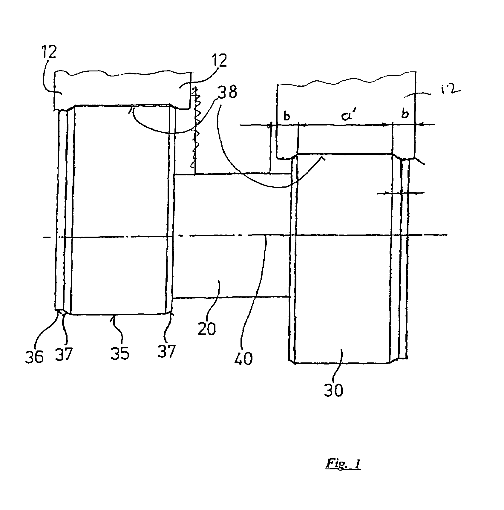
[0039]Referring to FIG. 1, shown therein is a more or less diagrammatically illustrated part of a camshaft, with a shaft axis 40 and a cylindrical shaft part 20 which is concentric thereto. That cylindrical shaft part 20 is firstly produced independently of the cam contour by milling or turning.

[0040]Shown on both sides of the cylindrical shaft part 20 are cams 30 which in terms of their profile are in mirror image relationship with each other but in other respects are identical in configuration, while however being displaced in a radial direction in opposite directions with respect to the shaft axis 40.

[0041]The cams 30 can be circular in axial view thereonto, but they may also be of another peripheral contour. The cams 30 comprise a cylindrical main part 35 whose edges are beveled on both sides along bevel faces 37. Also adjoining the bevel 37 at one side is a respective cylindrical part 36 which is of somewhat smaller diameter than the cylindrical main part 35 and which is also s...


PUM

PropertyMeasurementUnit
relief surfaceaaaaaaaaaa
rectangular shapeaaaaaaaaaa
radiusaaaaaaaaaa

Abstract

A milling cutter for machining camshafts includes a rotary disc and an annular row of cutting bits mounted in pockets formed in the disc. Each cutting bit includes a top surface having a pair of diagonally spaced raised portions. Cutting edges are formed where the top surface and the raised portions intersect side surfaces of the bit. The pockets are arranged along an edge of the disc where a cylindrical outer periphery of the disc intersects an end face of the disc. Each pocket is configured with an internal cavity for receiving a raised portion of an inactive cutting portion of the respective bit.

Description

BACKGROUND OF INVENTION[0001]The present invention concerns a cutting bit for camshaft milling cutters and a corresponding disc milling cutter for camshaft milling. Corresponding cutting bits are already known in the state of the art, which comprise a substantially cuboidal cutting body with an upper face and a lower face oriented substantially parallel to one another and which have side faces. Cutting edges are formed along the lines of intersection of side faces with the top side and / or the underside.[0002]The cutting bits can be rectangular, preferably square in plan view. When mutually oppositely disposed side faces of such cutting bits extend substantially parallel to each other, that generally involves a negative rake angle, by virtue of the necessity for providing a relief surface behind the cutting edge. Cutting bits or cutting inserts of that kind are therefore also referred to for the sake of brevity as “negative cutting bits”.[0003]If the upper face is smaller than the lo...

Claims


Application Information

Patent Timeline
Patent Type & Authority Patents(United States)
IPC IPC(8): B23C3/08B23C5/20B23C5/16B23C3/00B23C5/06B23D1/00
CPCB23C3/08B23C5/207B23C2200/081Y10T407/23B23C2215/16Y10T407/1908B23C2200/205B23C5/202
Inventor WERMEISTER, GUNTERGOTZ-WERNER, HEINZ
Owner SANDVIK INTELLECTUAL PROPERTY AB
Why Eureka
Try Eureka