Contour plunge milling

a technology of which is applied in the direction of milling equipment, metal-working machine components, manufacturing tools, etc., can solve the problem that the twisting and plunge milling completely contradicts the conventional straight plunge milling, and achieves the effect of reducing wear and tear and being closer in appearan

Inactive Publication Date: 2005-08-16
MONSANTO TECH LLC
View PDF20 Cites 3 Cited by
  • Summary
  • Abstract
  • Description
  • Claims
  • Application Information

AI Technical Summary

Benefits of technology

[0008]The present invention provides a plunge milling method wherein an axial cutting tool is moved both axially and transaxially while in engagement with the workpiece material. Thus, this method of “contour” plunge milling completely contradicts the conventional straight plunge milling characteristic of limiting “cutting” tool movement to only the axial direction. When compared to traditional plunge milling techniques, the method of the present invention has demonstrated dramatically increased (e.g., 200%) material removal rates, a significant reduction in wear-and-tear on the milling system, and an intermediate product shape that is much closer in appearance to a desired final profile. In some applications, contour plunge milling also can be used for finishing operations.

Problems solved by technology

Thus, this method of “contour” plunge milling completely contradicts the conventional straight plunge milling characteristic of limiting “cutting” tool movement to only the axial direction.

Method used


Image

  • Contour plunge milling
  • Contour plunge milling
  • Contour plunge milling

Examples


Embodiment Construction

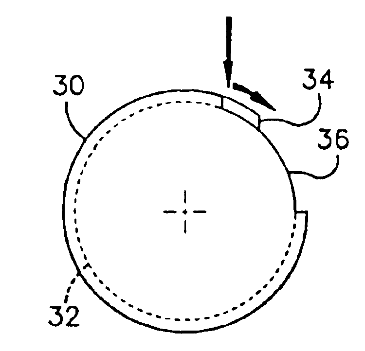
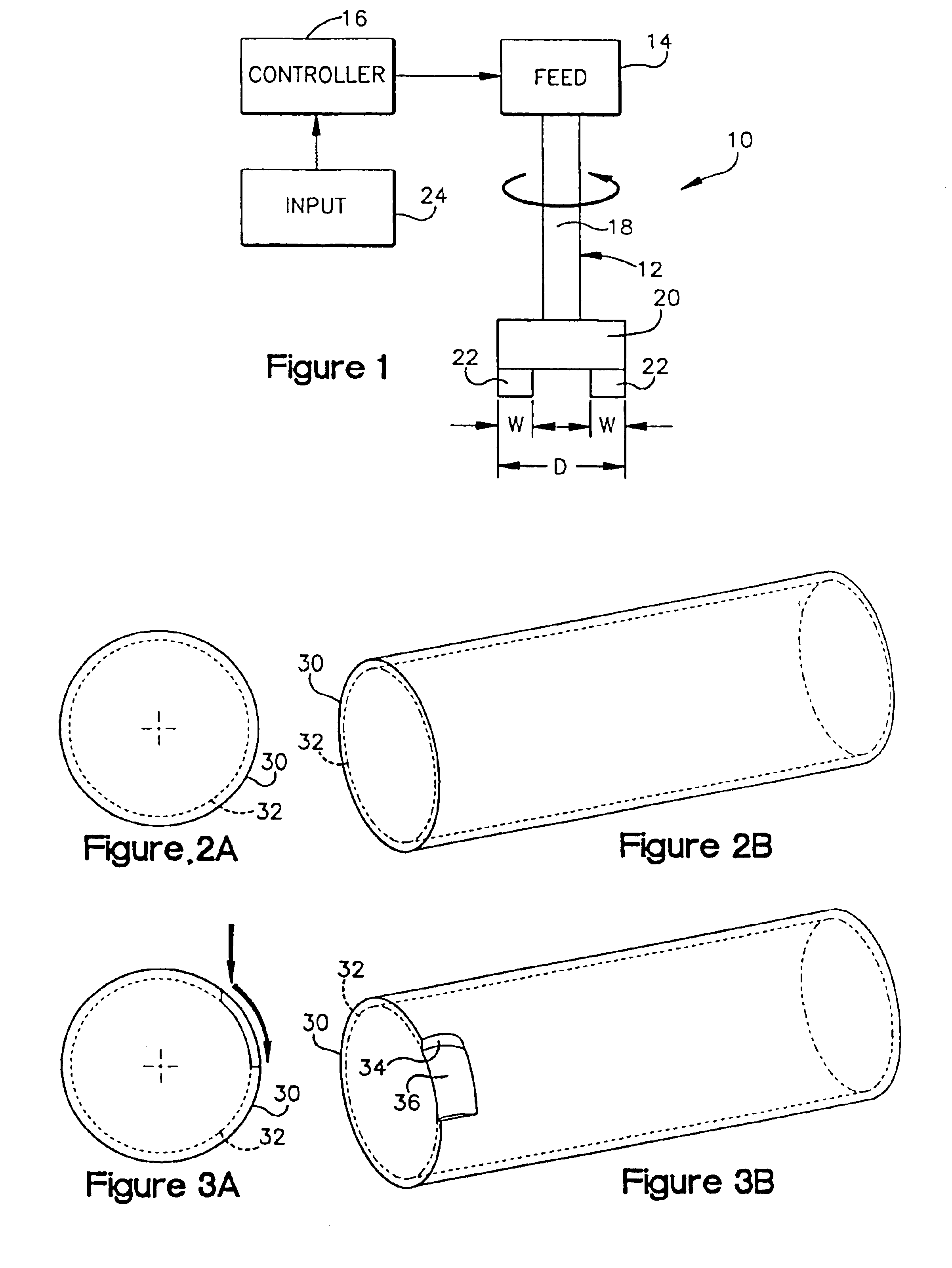
[0022]Referring now to the drawings in detail and initially to FIG. 1, a system 10 for practicing a plunge milling method according to the present invention is shown. Plunge milling is generally viewed as an extremely efficient method for removing large amounts of material (e.g., 20% to 60% or more) from a workpiece blank. The plunge milling method of the present invention is likewise extremely efficient and, moreover, has demonstrated dramatically increased (e.g., 500%) material removal rates when compared to conventional straight plunge milling methods.

[0023]The plunge milling system 10 comprises an axial cutting tool 12, a feed mechanism 14 for the tool 12, and a controller 16 which controls the feed mechanism 14. The plunge-cutting tool 12 comprises a spindle 18, a holder 20 attached to the spindle 18 for rotation therewith, and cutting elements 22 which are carried by the holder 20. The spindle 18 of the plunge-cutting tool 12 is attached to the feed mechanism 14 for controlled...


PUM

PropertyMeasurementUnit
lengthaaaaaaaaaa
movementaaaaaaaaaa
circumferenceaaaaaaaaaa

Abstract

A plunge milling system (10) for effecting rapid removal of material from a workpiece during a rough and/or finishing cutting procedure. In this system, an axial cutting tool (12) is rotated about its axis and axially moved into engagement with the workpiece for cutting material from the workpiece. When the tool (12) is engaged with the workpiece, the tool is also moved transaxially and simultaneously with the axial movement whereby material is removed from the workpiece along a curved path.

Description

RELATED APPLICATION DATA[0001]This application is a continuation of U.S. patent application Ser. No. 10 / 319,984 filed Dec. 16, 2002 now U.S. Pat. No. 6,726,413, which is hereby incorporated herein by reference.FIELD OF THE INVENTION[0002]This invention relates generally as indicated to a method of plunge milling for removing large amounts of material from a workpiece blank.BACKGROUND OF THE INVENTION[0003]Plunge milling is commonly viewed as an extremely efficient method for removing large amounts of material (e.g., 20% to 60% or more than traditional peripheral milling methods) from a workpiece blank. In such a milling process, a cutting tool is plunged axially and repeatedly into the workpiece blank in a series of overlapping passes to create an intermediate workpiece. The intermediate workpiece is then de-roughed and finished to create the final workpiece. Plunge milling is distinct from the more traditional peripheral milling methods where a cutting tool with one or more side cu...

Claims


Application Information

Patent Timeline
Patent Type & Authority Patents(United States)
IPC IPC(8): B23C3/00B23C3/02
CPCB23C3/00B23C3/02Y10T409/307112Y10T409/303808Y10T409/30756
Inventor STELSON, THOMAS SEMONJERROME, STEPHEN CURTISMEDITZ, ROBERT ALBIN
Owner MONSANTO TECH LLC
Why Eureka
Try Eureka