Variable view arthroscope

a variable view, arthroscope technology, applied in the field of arthroscopes and endoscopes, can solve the problems of limited useful scope of minimally invasive surgical techniques, limited range of arthroscopes, endoscopes and other principal optical instruments employed, etc., and achieve the effect of sealing more effectively

Inactive Publication Date: 2005-08-16
DURELL & GITELIS INC
View PDF39 Cites 19 Cited by
  • Summary
  • Abstract
  • Description
  • Claims
  • Application Information

AI Technical Summary

Benefits of technology

[0009]A variable view arthroscope in accordance with the present invention includes a housing and an input assembly. In various embodiments, the input assembly defines/determines the viewing position of the arthroscope. In certain embodiments, magnets link the external portion with the internal portion such that an external master magnet drives an internal slave magnet through the housing. In certain contemplated embodiments, external magnets rotate orthogonal to the longitudinal axis of the endoscope and drive internal magnets that are independ

Problems solved by technology

The value of using minimally invasive surgical techniques may be limited by the capabilities of the arthroscopes, endoscopes and other principal optical instruments employed.
In particular, the rather limited field of view afforded by even the best available instruments that satisfy the dimensional and other requirement of surgical applications has limited the useful scope of minimally invasive surgical techniques.
Designing the control mechanism is challenging because the components that manipulate the movable arrangement of optical elements must provide sufficiently precise control and fit in the arthroscope.
An additional challenge in designing the control mechanism is to minimize, and preferably eliminate, the risk of lea

Method used


Image

  • Variable view arthroscope
  • Variable view arthroscope
  • Variable view arthroscope

Examples


Embodiment Construction

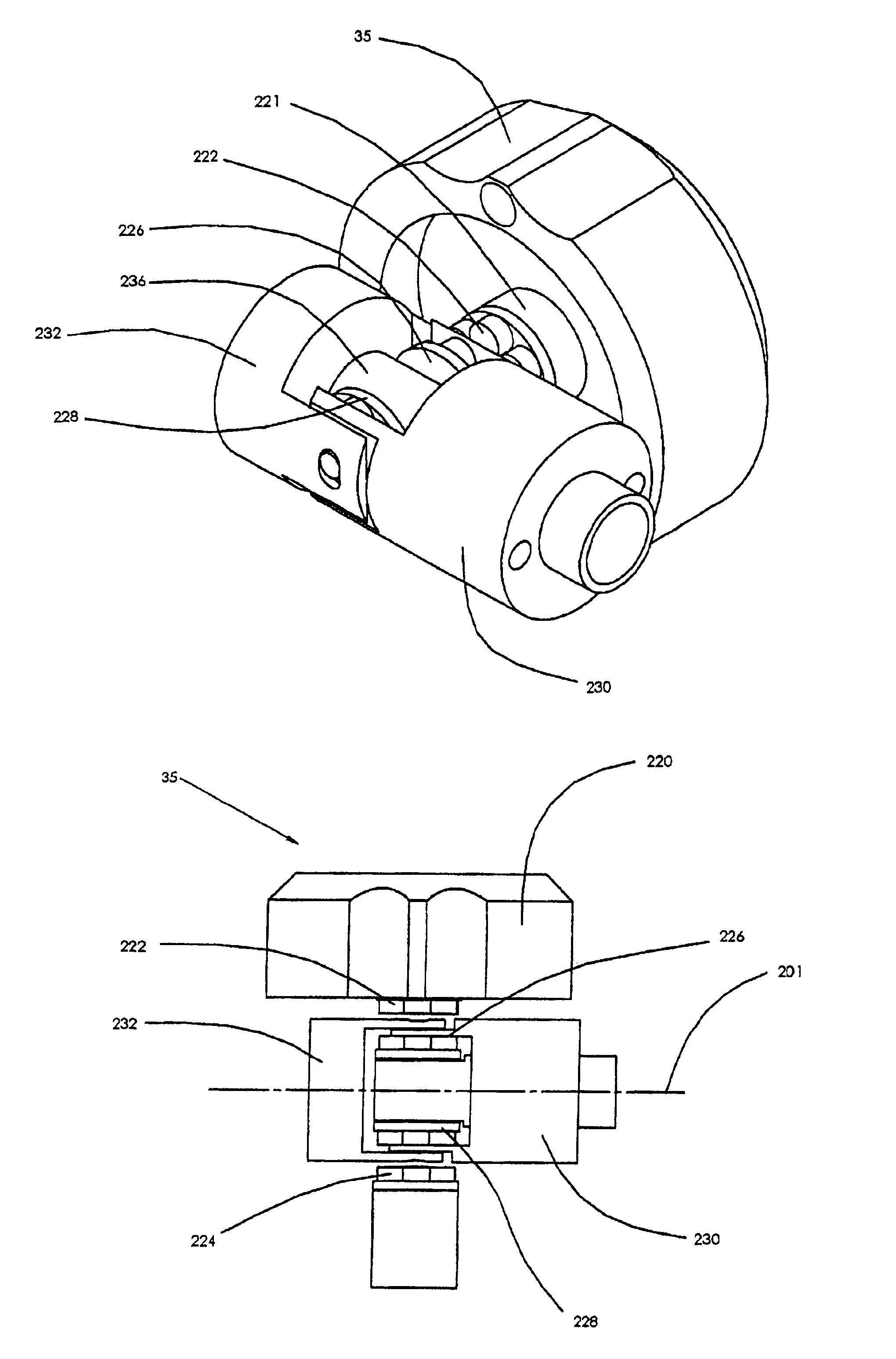
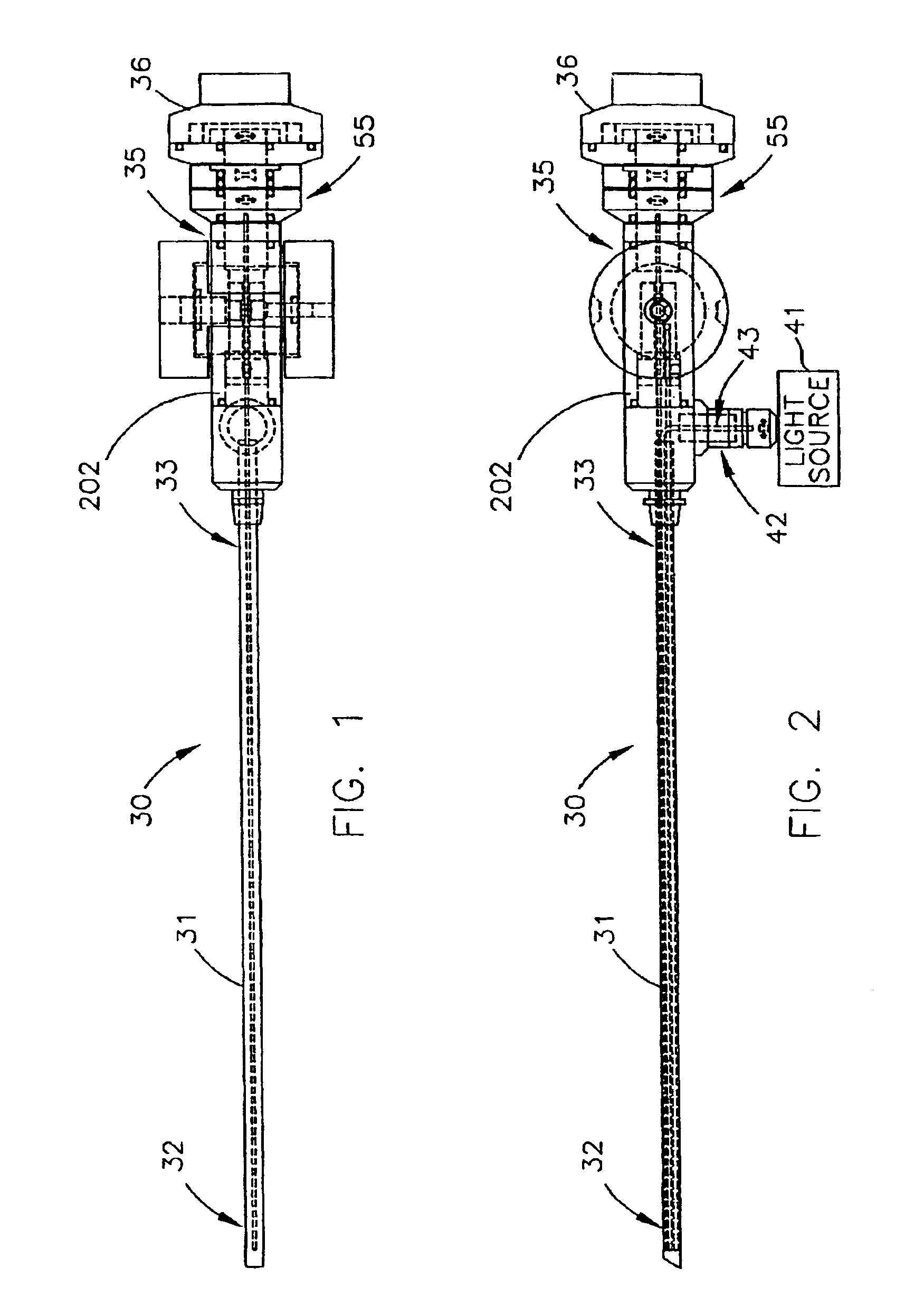
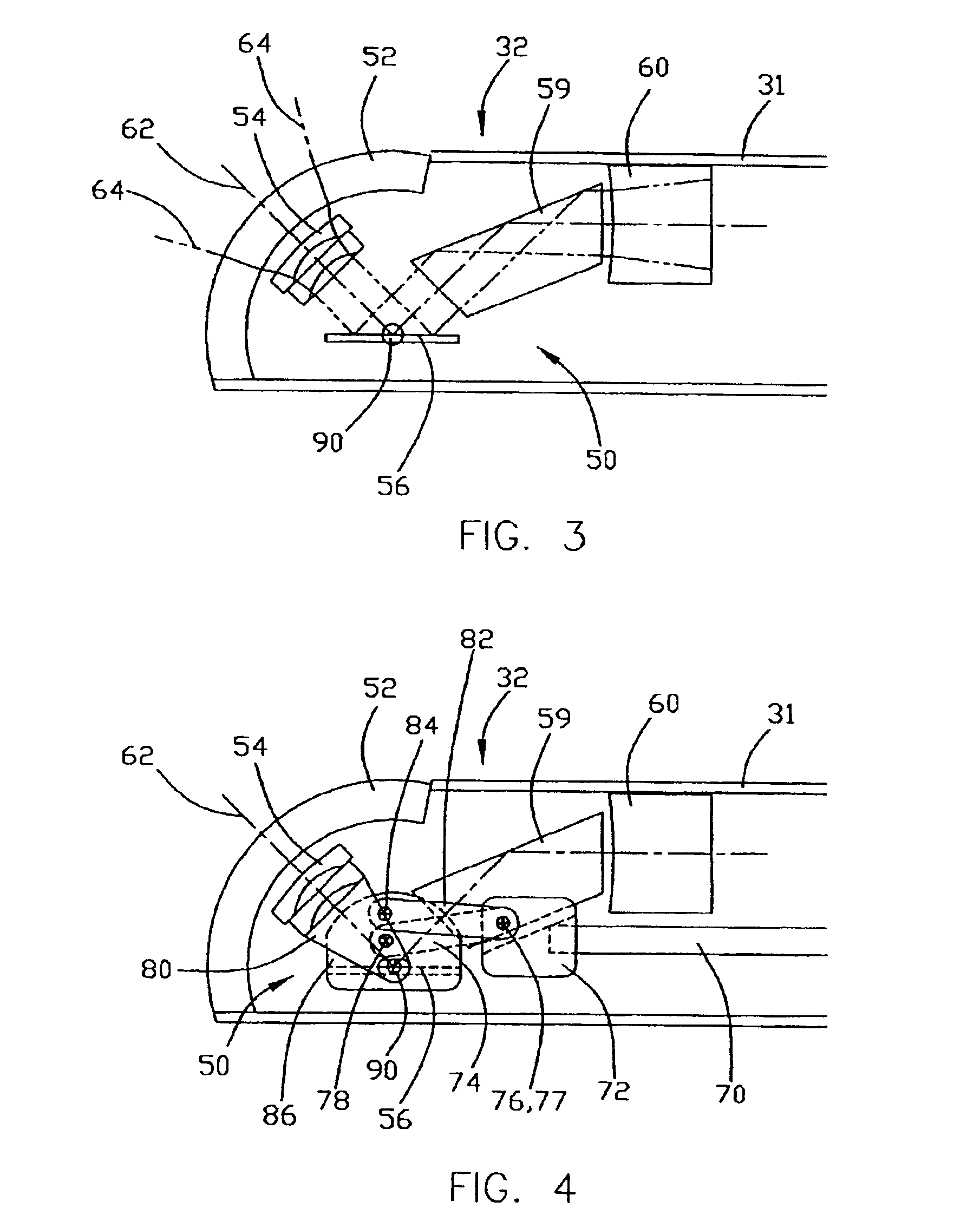
[0024]A variable view arthroscope in accordance with an embodiment of the present invention is shown in FIGS. 1 and 2. Although shown and described herein as an arthroscope providing up-down view variability, a similar configuration could be oriented so as to provide side-to-side view variability or view variability along any other axis. A variable view arthroscope, generally indicated at 30, includes an elongated housing tube 31, with an input end 32 and a control end 33, that extends along a central, longitudinal axis. Arthroscope 30 includes an outer control portion 35. Housing tube 31, and more specifically its control end 33, may extend into the outer control portion 35 of arthroscope 30. Generally, the object rays are captured at the input end 32 of housing tube 31, relayed to the control end 33, and recorded and displayed from the outer control portion 35 of arthroscope 30. As discussed herein, the object is formed of object rays and the object rays include an axial ray at th...


PUM


Abstract

A variable-view arthroscope or similar instrument (endoscope, etc.) includes a housing tube with an input end. The housing tube contains an input assembly and a portion of a light relay assembly. A control varies the position of the input assembly to change the viewing position of the arthroscope. In certain embodiments, the control uses external master magnets that rotate around an axis orthogonal to the longitudinal axis of the housing to drive internal slave magnets magnetically. This permits the housing to be sealed completely. In certain embodiments, a cam-axle assembly translates the rotational motion of the internal slave magnets to linear motion that drives a push rod that manipulates the input assembly.

Description

RELATED APPLICATIONS[0001]This application is a continuation-in-part of U.S. application Ser. No. 10 / 694,446, entitled Variable View Arthroscope with Charge Coupled Device filed Oct. 27, 2003, by inventor William E. Durell, which is a continuation-in-part of U.S. application Ser. No. 09 / 650,621, now issued as U.S. Pat. No. 6,638,216, entitled Variable View Arthroscope, filed Aug. 30, 2000 by inventor William E. Durell. The aforementioned applications are incorporated herein by reference.FIELD OF THE INVENTION[0002]The invention relates generally to arthroscopes, endoscopes and similar optical instruments and more specifically to variable view arthroscopes. The invention also relates to control mechanisms for medical devices.BACKGROUND OF THE INVENTION[0003]Arthroscopes and similar optical instruments, such as endoscopes, are used in medical applications, such as surgery and examination, as well as in non-medical applications that similarly involve visual inspection of a confined or ...

Claims


Application Information

Patent Timeline
IPC IPC(8): A61B1/00A61B1/317A61B1/313A61B1/06
CPCA61B1/00165A61B1/00183A61B1/317A61B1/0011
Inventor DURELL, WILLIAM E.
Owner DURELL & GITELIS INC
Why Eureka
Try Eureka