Method and a device for measuring concentrations

a concentration and concentration technology, applied in the field of concentration measurement methods and devices, can solve the problems of inability to give such information to the in-line meter, inability to base an in-line sensor on, and inability to meet the requirements of optical measurement principles, etc., to achieve the effect of improving accuracy, improving accuracy and improving reliability

Inactive Publication Date: 2005-08-16
BTG KAELLE INVENTING AKTIEBOLAG
View PDF10 Cites 23 Cited by
  • Summary
  • Abstract
  • Description
  • Claims
  • Application Information

AI Technical Summary

Benefits of technology

[0014]Thanks to the invention there do now exist a method and a device for measurement of concentration of especially pulp suspensions, said device is essentially cheaper, simpler in its structure, more reliable in running and has a larger efficiency concerning stirring / homogenizing, deaearation and deflocculation. All this gives a quicker, better and run-safer measuring information.

Problems solved by technology

However, specific measuring parameters often have to be determined on samples taken out from the measuring medium.
An in-line meter cannot always give such an information.
This can depend on the state of the suspension and / or on the actual design of the method, which is not suitable to base an in-line sensor upon.
At too high concentrations the optical measuring principle does not function satisfactory and there is in this case a risk that the measuring cell is plugged by the pulp.
However, there are evident limitations and / or drawbacks:For the task a relatively big, expensive and energy requiring pump is needed, which besides must be rotation speed regulated in order to obtain a suitable flow rate for the measurement through the measuring transducer and for control of the deaeration.
A too high rotation speed instead can create a vortex formation in the measuring vessel, so that air is sucked into the suspension.The tightening between the motor axle and the pump housing becomes easily untight and relatively often has to be changed.
The untightness means that air can be sucked into the suspension, which shall be measured, which spoils the measurement.The fibres of the pulp suspension in the pump housing can be broken or in another way be changed, so that the measuring results can be wrong.
Furthermore, during high rotation speeds in the pump housing cavitation effects can easily arise, so that disturbing air bubbles are created.
Dependent on the structure the pump housing can also be difficult to be deaerated at the time of each new measurement cycle.A pump based sample treatment unit requires a relatively large measuring vessel.

Method used


Image

  • Method and a device for measuring concentrations
  • Method and a device for measuring concentrations
  • Method and a device for measuring concentrations

Examples


Embodiment Construction

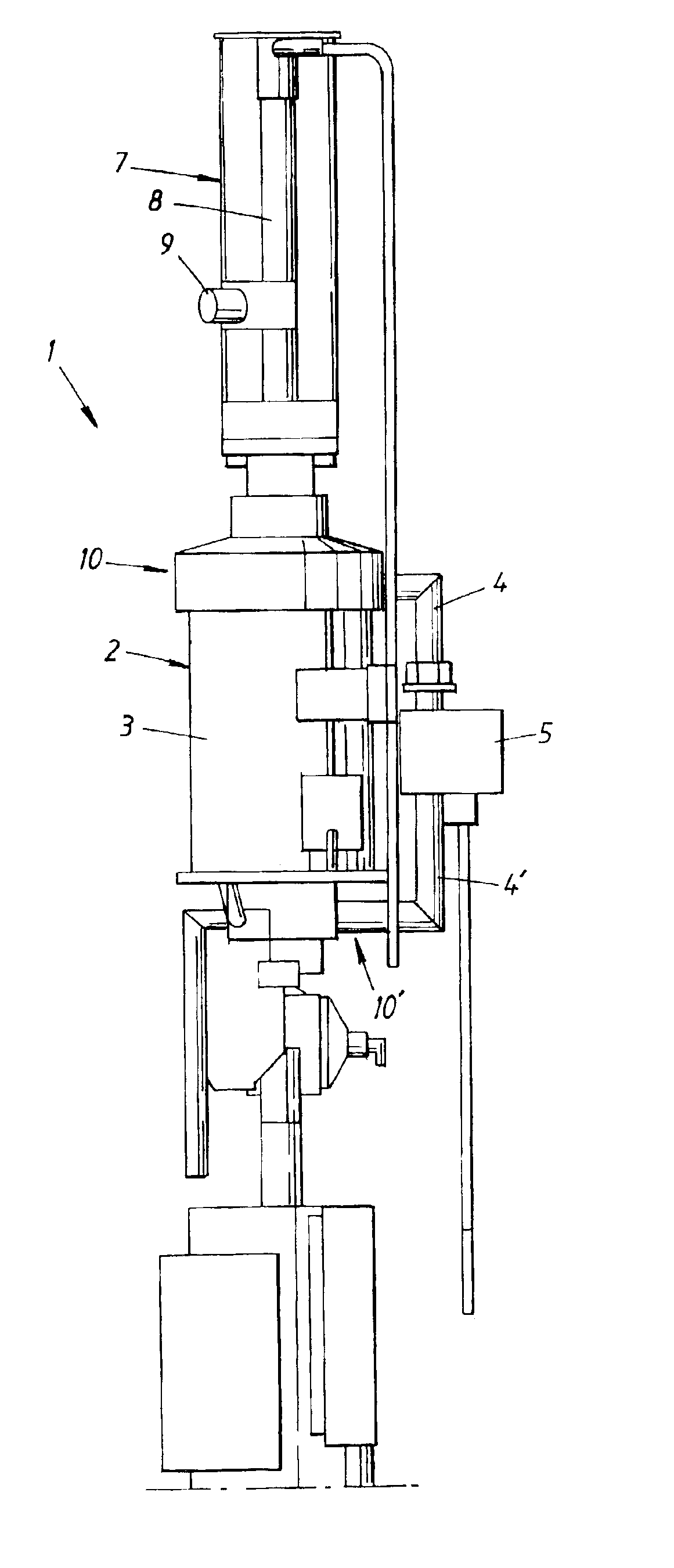
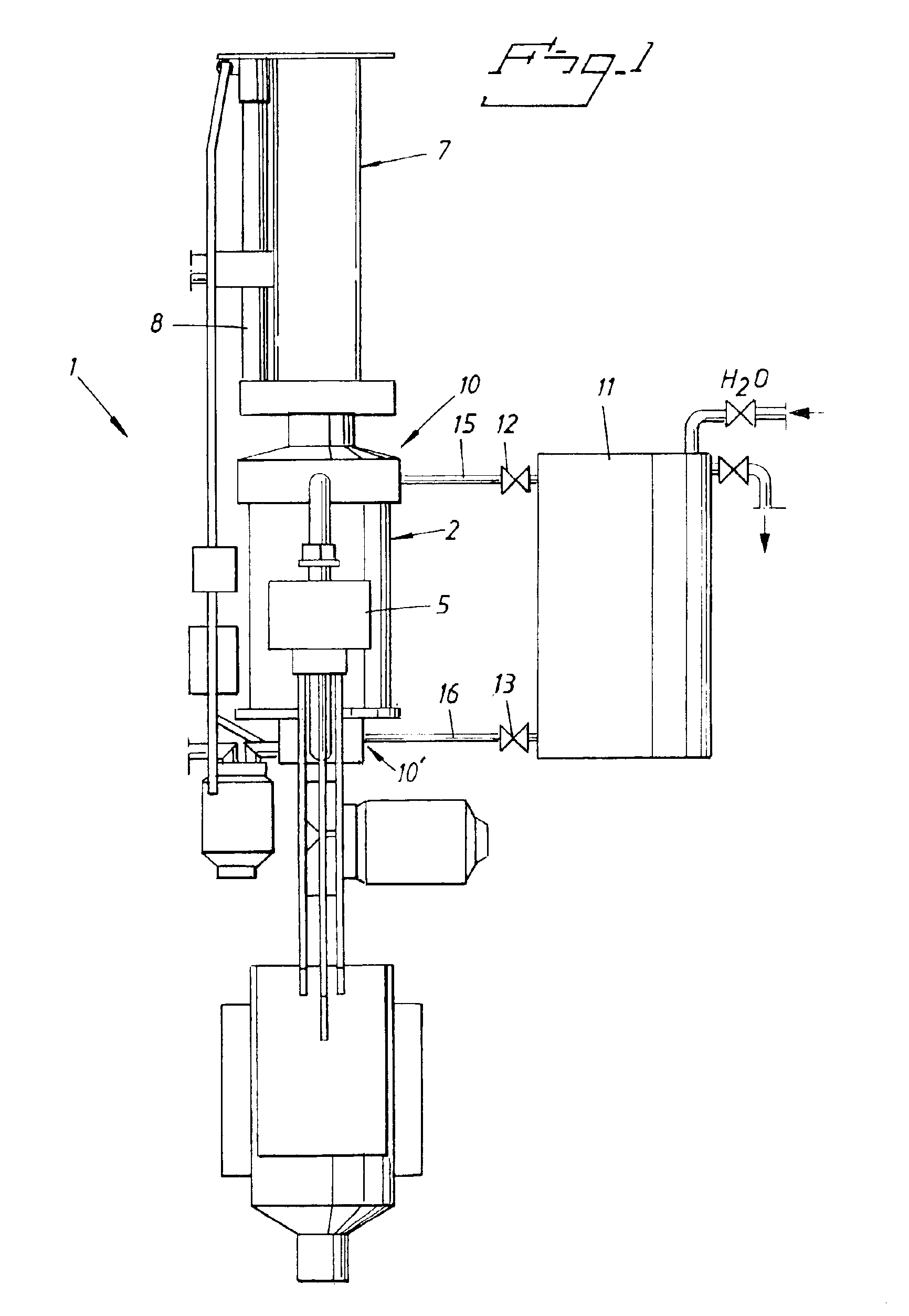
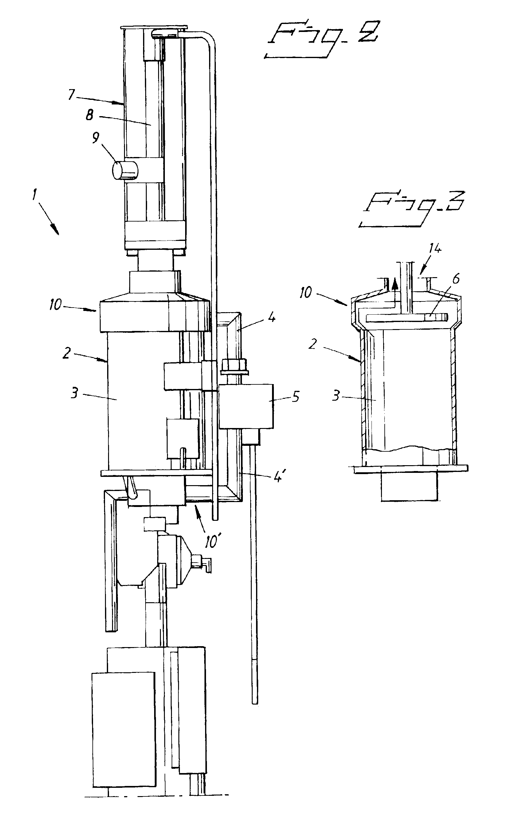
[0019]As can be seen from the drawings the invention refers to a device in the form of a sample treatment unit 1, which is based on a closed measuring vessel 2, which is filled completely with a measuring sample 3. At the side of the measuring vessel 2, which in the example illustrated is cylinderformed, communicating tubes 4 and 4′ are provided, which connect the upper part 10 and the lower part 10′ of the measuring vessel 2 to a measuring sensor 5. A piston 6 is guided upwards and downwards in the measuring vessel 2 via a pressure air cylinder 7, so that the measuring sample 3 is pressed through the measuring sensor 5 from each direction. The diameter of the piston 6 is mainly the same as the inner diameter of the measuring vessel 2. The flow rate is in a simple way controlled via the speed of the piston 6, which in its turn is controlled via the pressure of the used pressurized air, regulated by aid of a pressure reducing wave. The measurement can be done both during the movement...


PUM

PropertyMeasurementUnit
concentrationaaaaaaaaaa
speedaaaaaaaaaa
concentrationsaaaaaaaaaa

Abstract

A method and a device for measuring concentrations especially in a pulp suspension, from which a sample has been taken. The sample is collected in a measuring vessel, in which a piston is guided upwards and downwards in order to press the sample from each direction through a measuring sensor collected at the side of the measuring vessel via communicating tubes connected in an upper and a lower position to the measurement vessel, whereby the sample is stirred totally to eliminate flocculation in the same. Measurement of the concentration of the sample is made either during the upwards and downwards movement of the piston in the measuring vessel and first occurs when the speed of the sample through the measuring sensor is constant and the sample has been homogenized after at least some movement upwards and downwards of the piston.

Description

[0001]This application claims priority to application 0200221-0 filed in Sweden on Jan. 25, 2002.BACKGROUND OF THE INVENTION[0002]1. Field of the Invention[0003]The present invention refers to a method and a device for measuring concentrations preferably in pulp suspensions.[0004]2. Description of the Related Art[0005]Better control over processes in manufacturing industry is one solution in order to obtain a better productivity, better and new qualities and less influence on the surroundings. Therefore measuring on-line is absolutely a necessity. The measurement shows the connections between the process, the raw material and the finished product and gives an increased understanding for the dynamic of the process and with that a basis for taking up more effective control strategies. Measuring on-line can be done in different ways depending on the measuring method and the measuring sequence required. One method is measuring in-line where the measuring sensor is directly mounted in th...

Claims


Application Information

Patent Timeline
Patent Type & Authority Patents(United States)
IPC IPC(8): G01N33/34G01N11/00G01N11/08D21H23/78D21H23/00G01N1/00G01N15/06G01N1/10
CPCG01N11/08G01N33/343D21H23/78
Inventor FLADDA, GERDTWENG, JONNY
Owner BTG KAELLE INVENTING AKTIEBOLAG
Why Eureka
Try Eureka