
Encoder

a technology of encoder and encoder, which is applied in the direction of electric switches, basic electric elements, electric apparatus, etc., can solve the problems of large number of separate parts, complex assembly procedures, and certain drawbacks of the mechanical construction of these known devices

Inactive Publication Date: 2005-08-16
TECHTRONIC IND CO LTD
View PDF17 Cites 81 Cited by
  • Summary
  • Abstract
  • Description
  • Claims
  • Application Information

AI Technical Summary

Benefits of technology

[0005]It is an object of the present invention to provide an electromechanical roller-key assembly of simple and robust construction. The assembly may be integrated in electronic equipment and generate digital control signals in response to the instantaneous change in angular position of a user-operated roller.
[0007]It is a further object of the present invention to provide an electromechanical roller-key assembly comprising fewer and simpler mechanical parts compared to prior art roller-key assemblies, thereby making the present electromechanical roller-key assembly suitable for a simplified and automated factory assembly.
[0016]The switching means may be adapted to indicate the displaced position of the first member by forming an electrical connection between a protrusion of the first part of the frame and an electrical conductor or pad positioned in a fixed manner relative to the second part of the frame and / or relative to the external housing or casing or frame. This has the advantage that it provides a much simpler actuator switch element compared to prior art membrane switches.
[0020]The rotatably mounted cylindrically shaped first member may function as a user operated roller. The roller may comprise corrugated grooves disposed along a substantially axially oriented surface path on the end of the cylindrically shaped member opposite to the end that comprises the encoding disc. The grooves may be in contact with a spring member formed in the frame and provide a biasing force against the corrugated grooves, thereby providing a user op rating the roller with tactile feedback to assist the user in determining the angular rotation of the roller.

Problems solved by technology

However, the mechanical constructions of these known devices have certain drawbacks due to a large number of miniature movable and stationary parts, often including a tiny detent spring element.
This large number of separate parts requires a quite complex and labour intensive assembly procedure to assure that all parts are carefully aligned with respect to each other.

Method used


Image

  • Encoder
  • Encoder
  • Encoder

Examples


Embodiment Construction

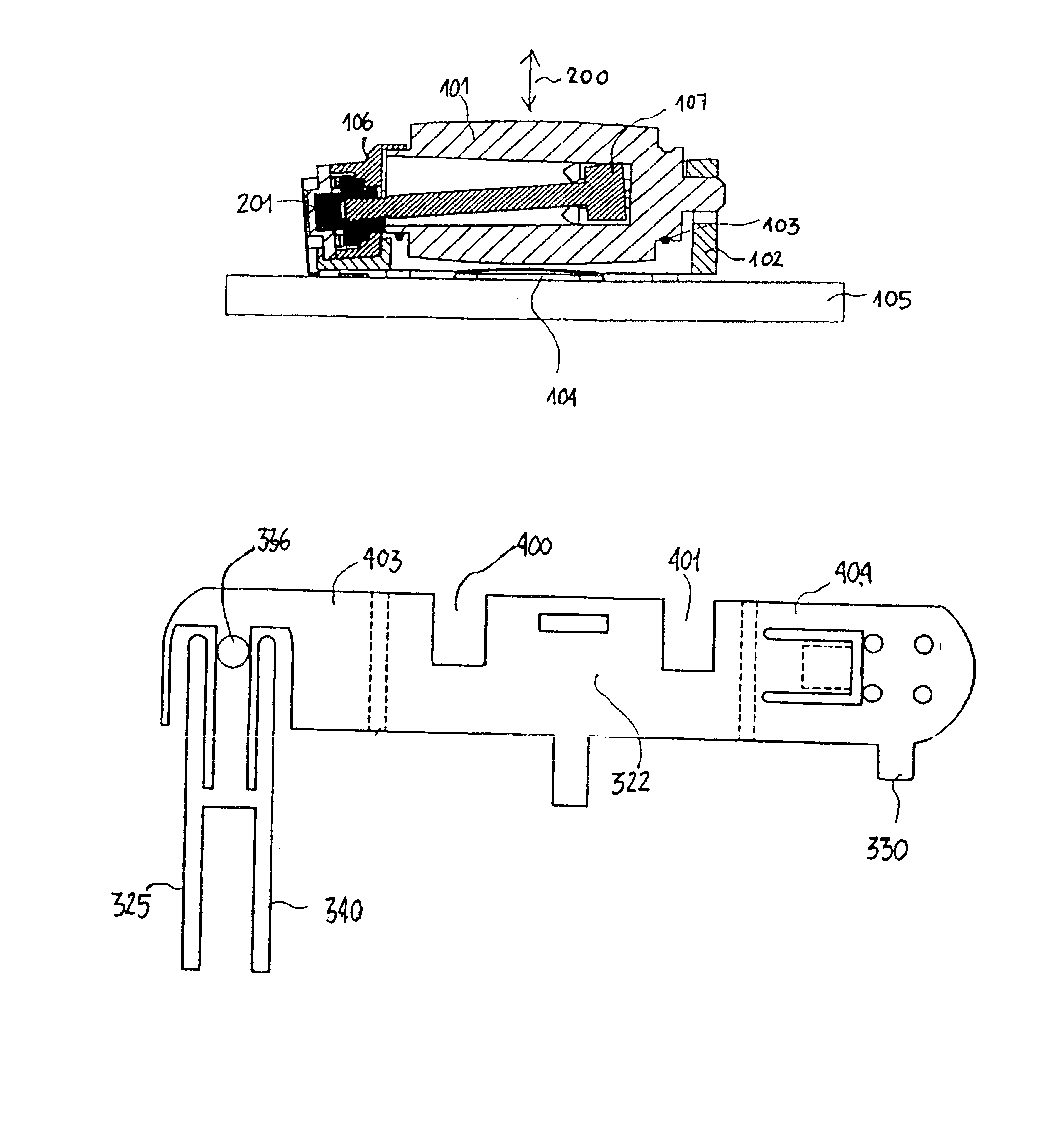
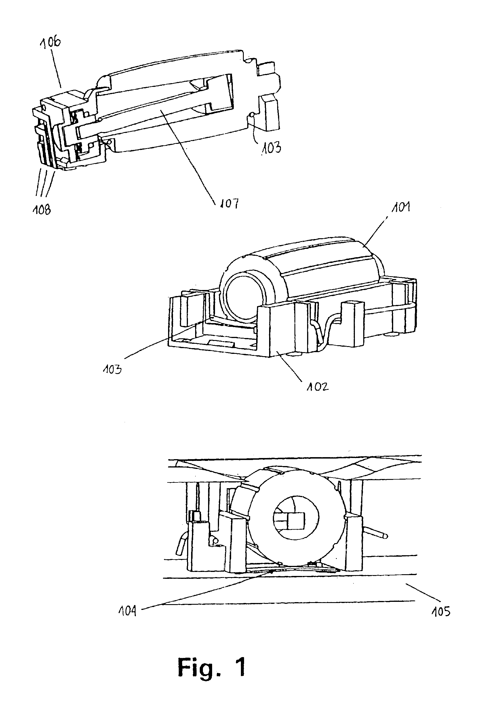
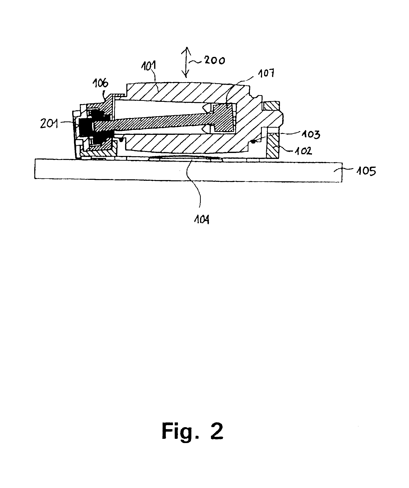
[0038]FIG. 1 shows various views of an electromechanical roller-key assembly according to a first preferred embodiment of the invention. A plastic moulded cylindrical roller 101 is rotatably mounted in a supporting frame 102. A detent spring 103 is also mounted on the frame and further attached to or abutting the roller in a manner that allows the roller to return to a rest position after it has been vertically depressed in order to activate a membrane switch 104 which may be positioned be low the roller on e.g. a printed circuit board (PCB) 105. The rotation of the roller is transferred to a coding member 201 (FIG. 2) housed in an encoding module 106 by means of a shaft 107 that provides a relatively rigid connection between the roller and the coding member.

[0039]FIG. 2 illustrates that predetermined clearance is provided at both ends of the shaft 107, this clearance provides a mechanism that allows the roller 101 to move vertically (in the direction illustrated by arrow 200) witho...


PUM


Abstract

The present invention relates to an electromechanical roller-key assembly of simple and robust construction. The assembly may be integrated in electronic equipment and generate digital control signals in response to an instantaneous change in angular position of a user-operated roller. The roller-key assembly according to the present invention is suitable for being manufactured with very small outer dimensions and with fewer and simpler mechanical parts compared to prior art roller-key assemblies, thereby making the roller-key assembly suitable for a simplified and automated factory assembly.

Description

FIELD OF THE INVENTION[0001]The present invention relates to encoder-switch assemblies such as electromechanical roller-key assemblies that comprise an encoder part and an actuator switch. The encoder part may operate according to magnetic, optical and / or electromechanical principles and may provide one or several electrical output signals indicating the instantaneous change of angular position of a rotating roller or tuning wheel of the encoder part of the encoder-switch assembly.[0002]The encoder-switch assemblies according to the present invention are particularly well adapted for use in mobile phones or, generally, in any type of electronic equipment that will benefit from the very small outer dimensions and simple construction of the encoder-switch assemblies.BACKGROUND OF THE INVENTION[0003]Electromechanical roller-key assemblies may be used to generate digital control signals in response to a rotation of a roller or tuning knob and to generate an actuator switch signal in res...

Claims


Application Information

Patent Timeline
Patent Type & Authority Patents(United States)
IPC IPC(8): H01H25/00H01H19/00H01H19/58H01H25/06
CPCH01H19/005H01H25/008H01H2019/146
Inventor JORGENSEN, MARTIN BONDORAVNKILDE, SOREN
Owner TECHTRONIC IND CO LTD
Learn More