Solar central receiver with inboard headers

a solar receiver and header technology, applied in the direction of machines/engines, mechanical equipment, light and heating equipment, etc., can solve the problems of bending the tubes in this manner to fill the gaps, loss of absorbed solar energy and possible damage to the interior components of the solar receiver, and difficult direct insulate the headers that face outward toward the concentrated solar flux

Active Publication Date: 2005-08-23
SOLARRESERVE TECH
View PDF8 Cites 62 Cited by
  • Summary
  • Abstract
  • Description
  • Claims
  • Application Information

AI Technical Summary

Benefits of technology

[0009]The present invention overcomes the deficiencies of the prior art by providing a solar receiver free of gaps between adjacent receiver panels. Specifically, the present invention eliminates gaps between the headers, tubes, and strong-backs of adjacent receiver panels by staggering or beveling the receiver panel headers, thus permitting the adjacent receiver panels to be placed closer together to fill any gaps between them. In the staggered configuration the headers of adjacent receiver panels are located at different elevations so that the headers overlap but do not contact each other, thus permitting the tubes and strong-backs of adjacent receiver panels to be positioned closer together to eliminate any gaps between the tubes and strong-backs of the adjacent panels. In the beveled configuration the headers are angled such that the terminal ends of adjacent headers are disposed parallel to one another when assembled onto a support structure of the solar receiver. The terminal ends are further positioned in closely abutting relationship, thus eliminating any gaps between adjacent headers, tubes, and strong-backs. The use of a staggered or beveled header configuration is also advantageous as it eliminates any need to use complicated, expensive, and time consuming tube bending techniques and designs to fill gaps between the tubes of adjacent receiver panels.

Problems solved by technology

Headers that face outward toward the concentrated solar flux are difficult to directly insulate due to the high temperature and damage imposed by the solar flux spillage that contacts these headers.
Passage of solar energy through these gaps results in a loss of absorbed solar energy and possible damage to the interior components of the solar receiver.
However, bending the tubes in this manner to fill the gaps is undesirable because it is complicated, time consuming, and costly.

Method used


Image

  • Solar central receiver with inboard headers
  • Solar central receiver with inboard headers
  • Solar central receiver with inboard headers

Examples


Embodiment Construction

[0017]The following description of the preferred embodiments is merely exemplary in nature and is in no way intended to limit the invention, its application, or uses.

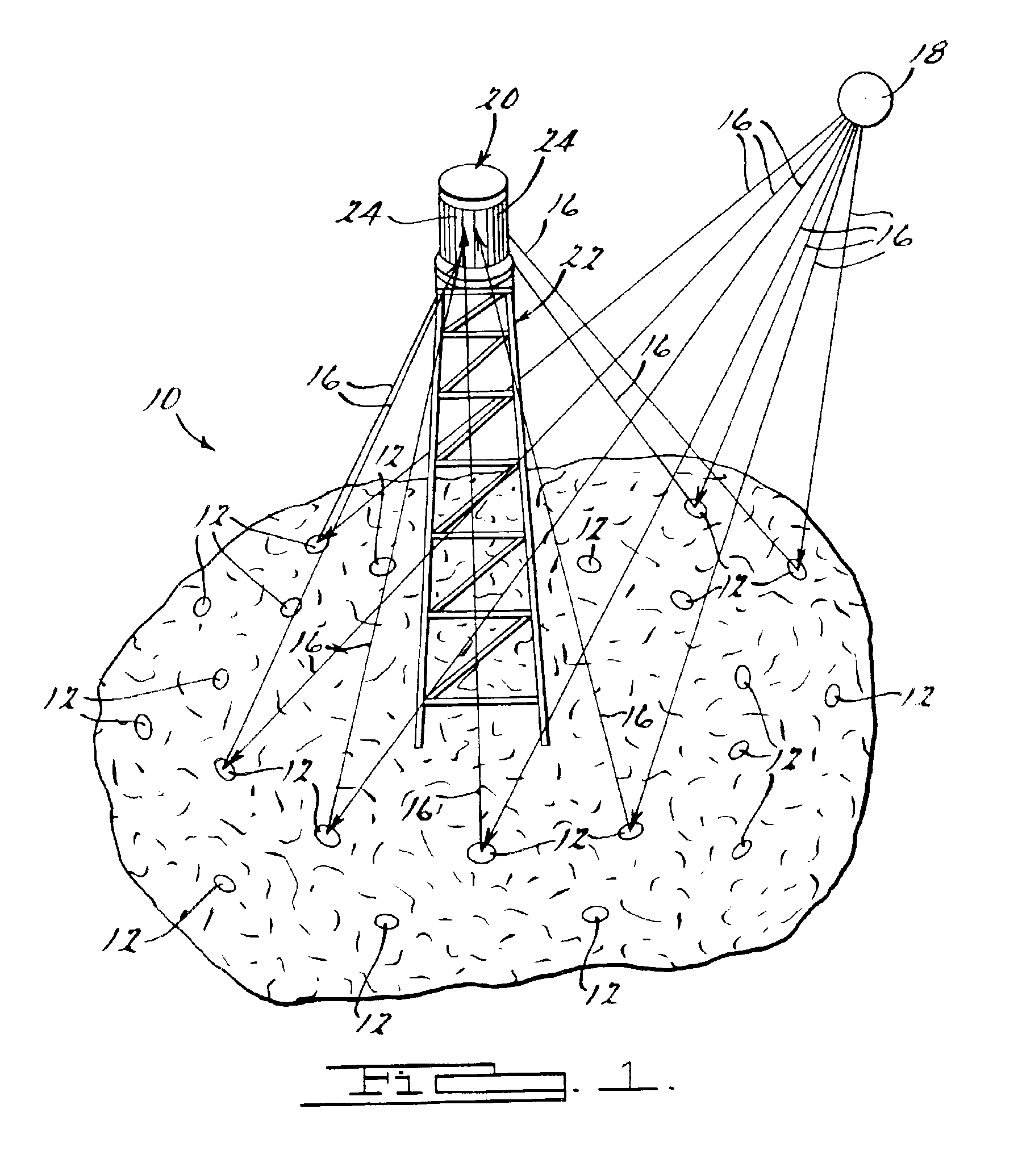
[0018]Referring to FIG. 1, a solar power plant according to the present invention is generally shown at 10. The solar power plant 10 includes a plurality of heliostats 12 positioned about a heliostat field 14. The heliostats 12 are generally reflectors, preferably in the form of mirrors, that reflect a plurality of energy rays 16 originating from a solar source 18. The heliostats 12 reflect the solar energy rays 16 from the solar source 18 upon a solar receiver 20.

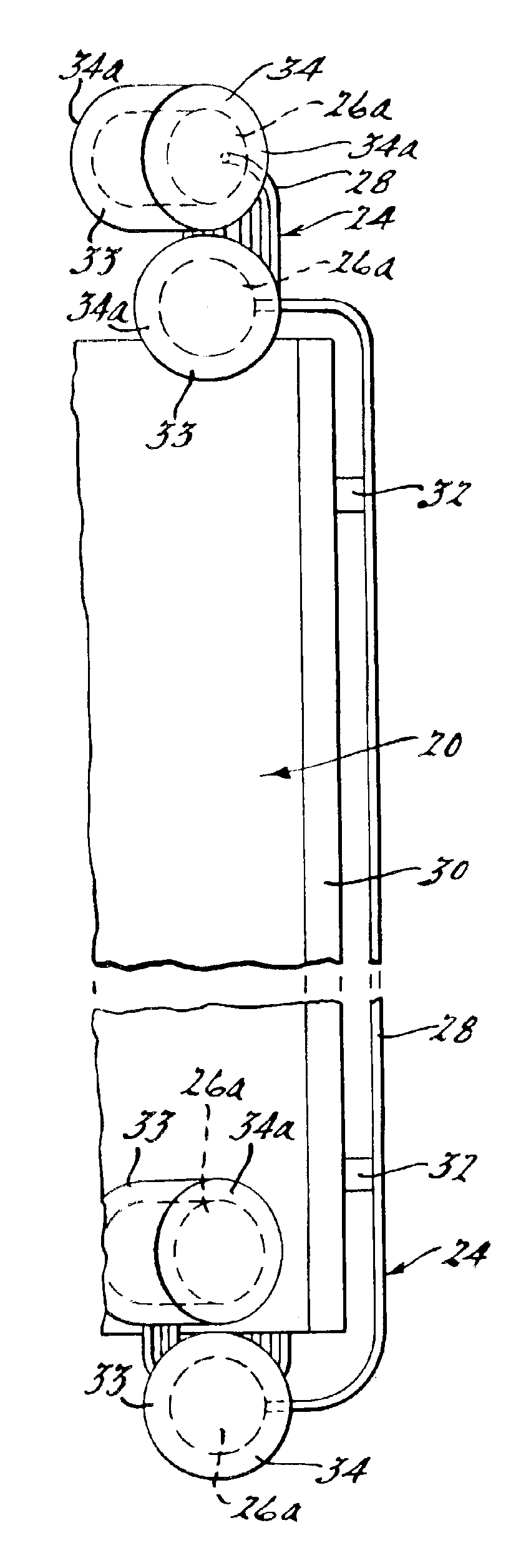
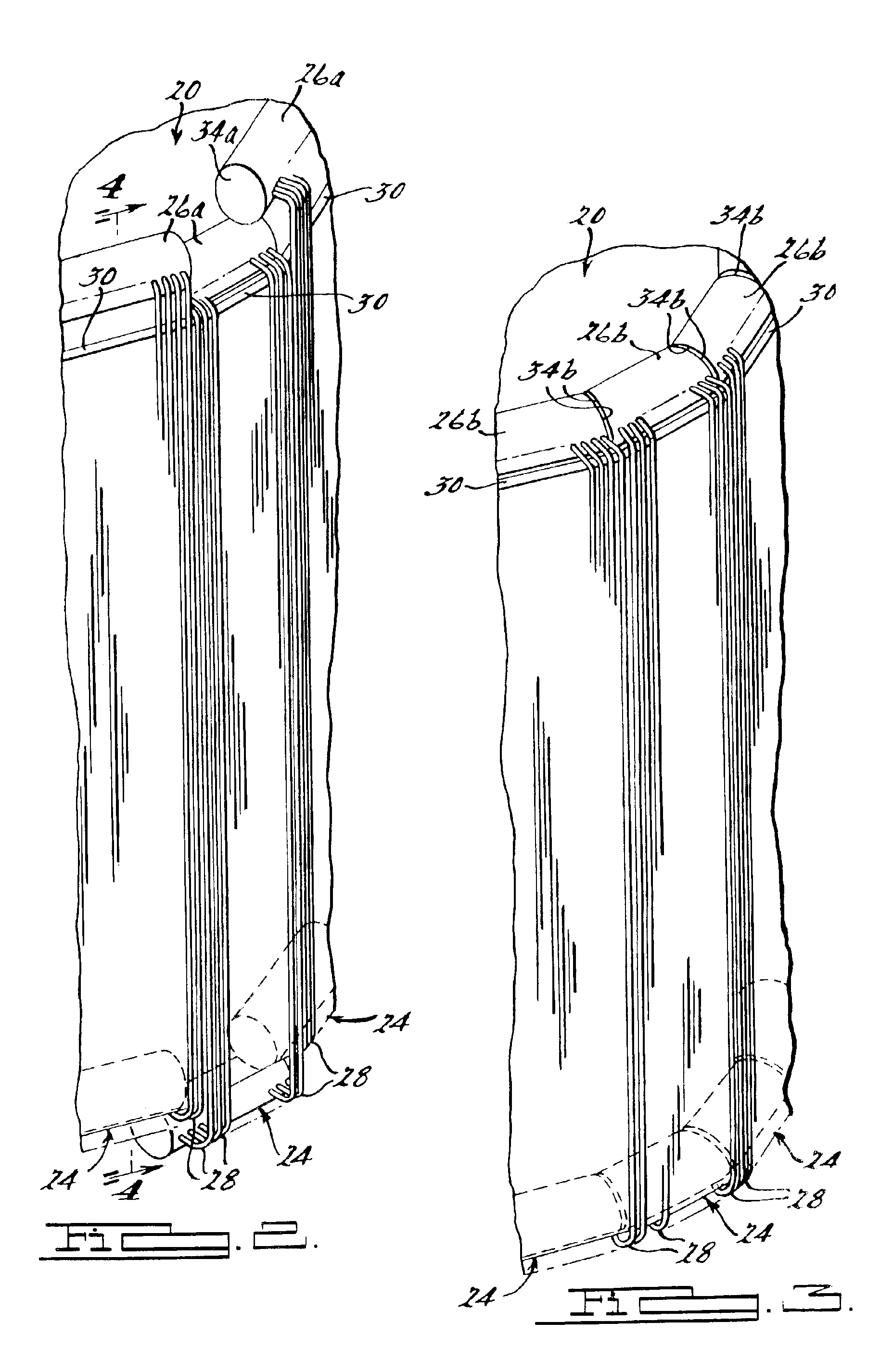
[0019]The solar receiver 20 is preferably cylindrical and positioned atop a tower 22. The tower 22 is preferably located at the approximate center of the heliostat field 14. Mounted about the solar receiver 20 are a plurality of solar receiver panels 24. As seen in FIGS. 2 through 5, each receiver panel 24 is generally comprised of two headers 26 connected by ...


PUM


Abstract

A solar power plant having a plurality of receiver panels mounted in a circular fashion about a solar receiver. Each receiver panel includes a plurality of tubes that terminate at each end at a header. To eliminate the presence of gaps between the tubes of adjacent receiver panels the headers are staggered or beveled. In the staggered configuration the headers of adjacent receiver panels are located in different elevations so that the headers of adjacent receiver panels may overlap each other, thus allowing the headers and tubes of adjacent receiver panels to be positioned closer together to eliminate gaps between the tubes of adjacent panels. In the beveled configuration the headers are angled such that the terminal ends of adjacent headers are parallel and positioned in a closely abutting relationship, resulting in the absence of gaps between adjacent headers and tubes.

Description

FIELD OF THE INVENTION[0001]The present invention relates to a solar central receiver power tower plant. More particularly, the present invention relates to an improved header design for a solar central receiver.BACKGROUND OF THE INVENTION[0002]Solar central receiver power plants are used to convert the sun's solar thermal energy into electrical energy for connection to a utility grid. Specifically, solar central receiver power plants intercept the sun's thermal energy using a collector system that includes a field of thousands of sun tracking mirrors called heliostats. The heliostats redirect and concentrate the solar thermal energy onto a circular, tower mounted, heat exchanger called a solar receiver. A plurality of planar receiver panels are positioned about the solar receiver for receiving the concentrated solar thermal energy.[0003]The receiver panels each include a plurality of elongated tubes mounted to a suitable strong-back. The elongated tubes terminate at each end in a h...

Claims


Application Information

Patent Timeline
Patent Type & Authority Patents(United States)
IPC IPC(8): F24J2/24F24J2/06F24J2/07F24J2/04F24S10/70F24S20/20
CPCF24J2/07F24J2/245F24J2/4649Y02E10/41Y02E10/44Y02E10/46F24S10/742F24S20/20F24S80/20Y02E10/40
Inventor LITWIN, ROBERT Z.
Owner SOLARRESERVE TECH
Why Eureka
Try Eureka