
Ferromagnetic/fluid valve actuator

a fluid valve actuator and actuator technology, applied in the direction of diaphragm valves, valve details, valve arrangements, etc., can solve problems such as resistance increase, and achieve the effect of less flow resistance and further energy saving

Inactive Publication Date: 2005-08-23
ARICHELL TECH INC
View PDF76 Cites 32 Cited by
  • Summary
  • Abstract
  • Description
  • Claims
  • Application Information

AI Technical Summary

Benefits of technology

This approach results in significant energy savings by reducing the current required for actuation and shortening the time needed for plunger movement, while maintaining efficient magnetic force generation.

Problems solved by technology

But we have recognized that selectively relieving the armature and / or pocket wall can actually save energy in small actuators, even though it results in some reluctance increase.

Method used


Image

  • Ferromagnetic/fluid valve actuator
  • Ferromagnetic/fluid valve actuator
  • Ferromagnetic/fluid valve actuator

Examples


Embodiment Construction

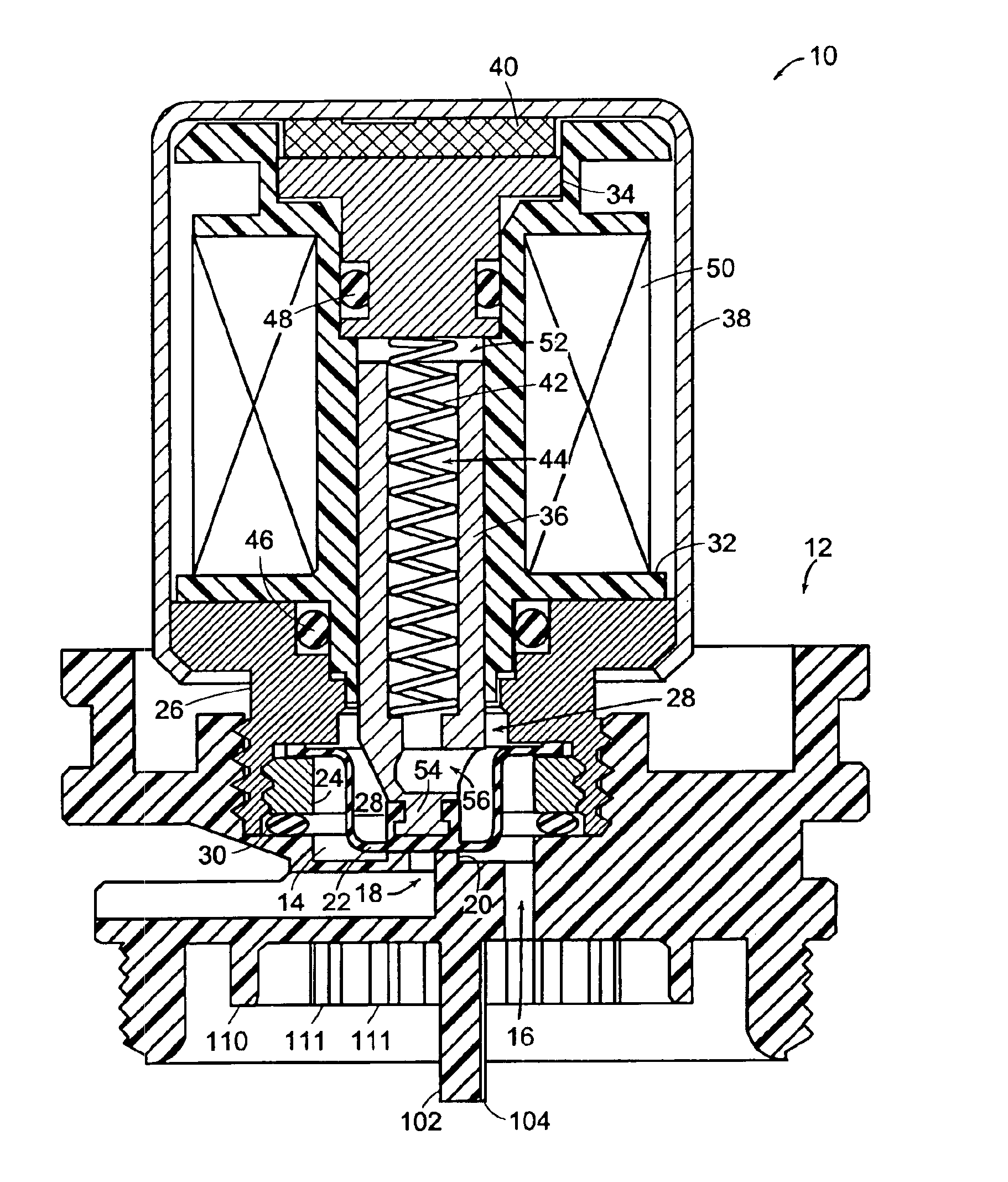
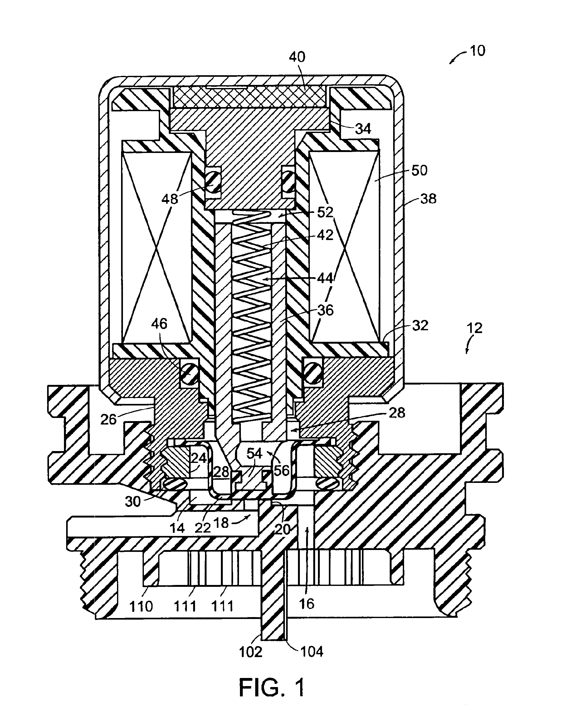
[0022]FIG. 1 depicts an actuator 10 threadedly secured to a pilot-valve body 12. Together with the actuator 10, the pilot-valve body 12 forms a pilot-valve chamber 14. The pilot-valve body member 12 forms an inlet passage 16 by which fluid enters the pilot-valve chamber, and it also forms a pilot-valve outlet passage 18 by which fluid can leave the chamber when the pilot valve is open.

[0023]The pilot-valve body also forms an annular valve seat 20 past which fluid must flow to leave the pilot-valve chamber 14 through the outlet 18. In the state that FIG. 1 illustrates, though, the actuator 10's flexible diaphragm 22 is seated on the valve seat 20 and thereby prevents such flow: the pilot valve is closed. A washer 24 threadedly secured to the actuator 10's front pole piece 26 traps the diaphragm 22's outer end against that pole piece. The diaphragm thereby isolates a chamber 28 from the fluid in the pilot-valve chamber. An O-ring 30 similarly prevents the fluid in the pilot-valve cham...


PUM


Abstract

A solenoid plunger (36) is disposed for reciprocation in a plunger pocket that is formed by the stationary parts of a solenoid-type actuator (10). A flexible diaphragm (22) closes the plunger pocket's open mouth and is deformed by movement of a plunger (36) between an open position, in which it is displaced from a valve seat (20), and a closed position, in which it is seated on the valve seat and thereby prevents flow from a valve inlet (16) to a valve outlet (18). The diaphragm thereby isolates the plunger from the fluid thereby being controlled, but a separate, incompressible fluid fills the chamber in which the plunger reciprocates. A through-plunger passage (44, 56) provides a low-flow-resistance path for the incompressible fluid to flow into and out of the portion (52) of the plunger chamber behind the plunger as the plunger moves. This reduces actuation time and thus the energy required for an actuation. The chamber in which the plunger reciprocates is formed by elements (22, 26, 32, and 34) through which the incompressible fluid can diffuse only very slowly, so the actuator can be long-lived even if it small in size.

Description

CROSS-REFERENCE TO RELATED APPLICATION[0001]The present application is a continuation-in-part of commonly assigned U.S. patent application Ser. No. 09 / 696,154, which was filed on Oct. 25, 2000, now U.S. Pat. No. 6,609,695 by Parsons et al. for a Ferromagnetic / Fluid Actuator and is hereby incorporated by reference.BACKGROUND OF THE INVENTION[0002]1. Field of the Invention[0003]The present invention concerns solenoid-type actuators and in particular actuators of the type whose armatures are disposed in fixed-volume sealed chambers.[0004]2. Background Information[0005]Electromagnetically operated valves ordinarily employ solenoid-type actuators. An armature, often referred to as a “plunger” in valve-type applications, is so disposed in a guide as to allow it to reciprocate. The plunger includes ferromagnetic material that forms part of the path taken by magnetic flux that results when current flows in a solenoid coil. The magnetic path's reluctance varies with plunger position. In acco...

Claims


Application Information

Patent Timeline
Patent Type & Authority Patents(United States)
IPC IPC(8): F16K31/08F16K7/12F16K7/16F16K31/06F16K7/14
CPCF16K7/14F16K7/16F16K31/06F16K31/082F16K31/0672
Inventor HERBERT, KAYGULER, FATIHPARSONS, NATAN E.
Owner ARICHELL TECH INC
Learn More