Al technical title is built by PatSnap Al team. It summarizes the technical point description of the patent document.
a card printer and cartridge technology, applied in the field of identification card printers, can solve the problems of adversely affecting the print quality, other printing, and the inability of the cardholder to protect the card from the environmen
Inactive Publication Date: 2005-08-23
ASSA ABLOY AB
View PDF140 Cites 86 Cited by
Summary
Abstract
Description
Claims
Application Information
AI Technical Summary
This helps you quickly interpret patents by identifying the three key elements:
Problems solved by technology
Method used
Benefits of technology
[0007]The present invention is directed to a card cartridge for use with an identification card printer that protects a stack of cards stored therein from environmental contamination while supporting them in a substantially flat plane to prevent the cards from warping. The card cartridge includes a housing having a pair of opposing side walls, a top, a front wall, a back wall opposite the front wall, and a base. The housing includes an interior cavity that is sized to accommodate a stack of cards. The housing also includes a card access and a card output slot. The card access allows a card transport mechanism to engage a lead card contained in the housing and feed the lead card through the card output slot.
Problems solved by technology
Unfortunately, these open card holders do not protect the cards from the environment.
As a result, dust and other particles can contaminate surfaces of the cards which can adversely affect the print quality and cause other printing problems.
Additionally, typical card holders of the prior art fail to support the cards in a flat plane, which can cause the cards to become warped resulting in misfeeds and poor printing.
Method used
Image
Click on the blue label to locate the original text in one second.
Reading with bidirectional positioning of images and text.
Examples
Embodiment Construction
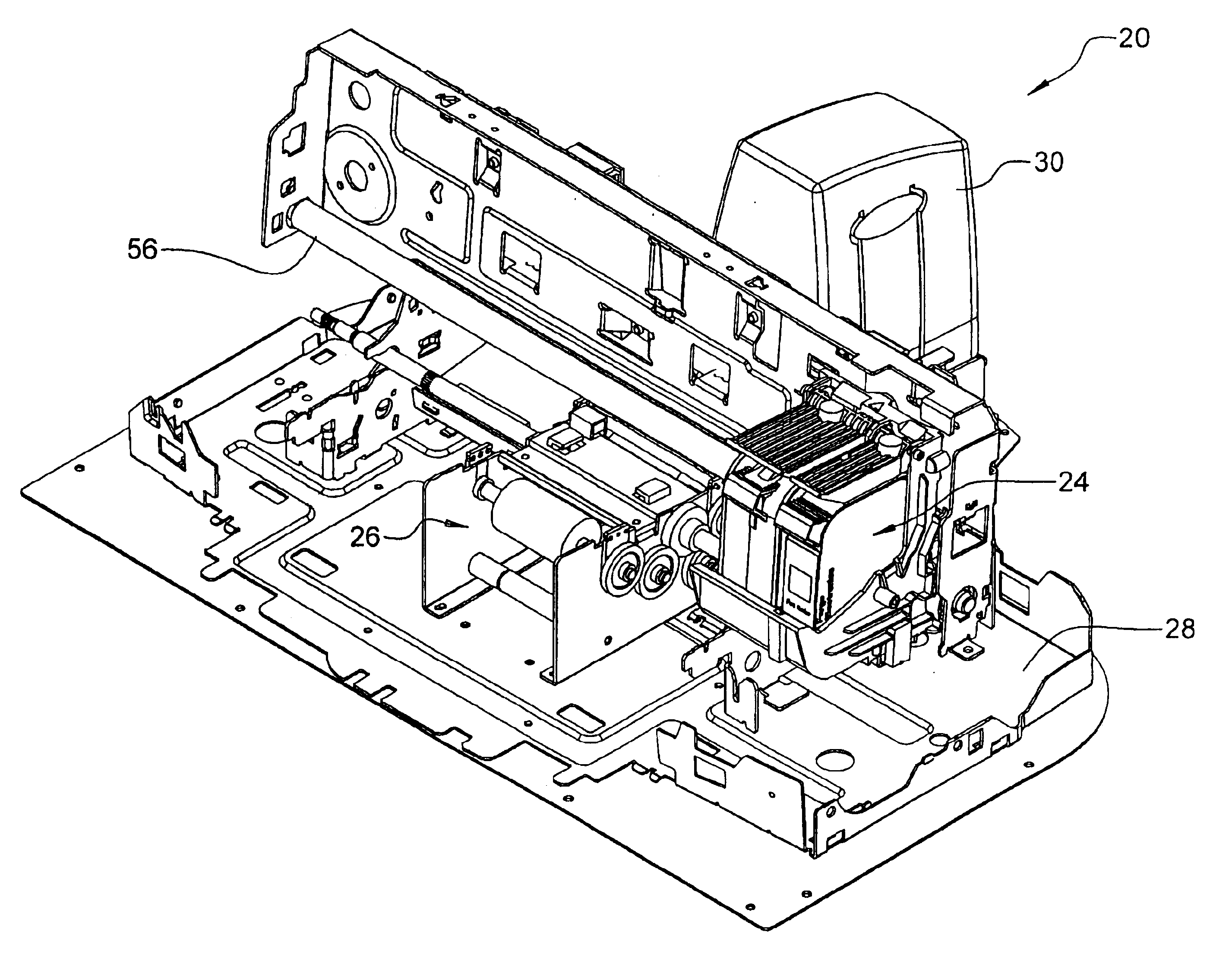
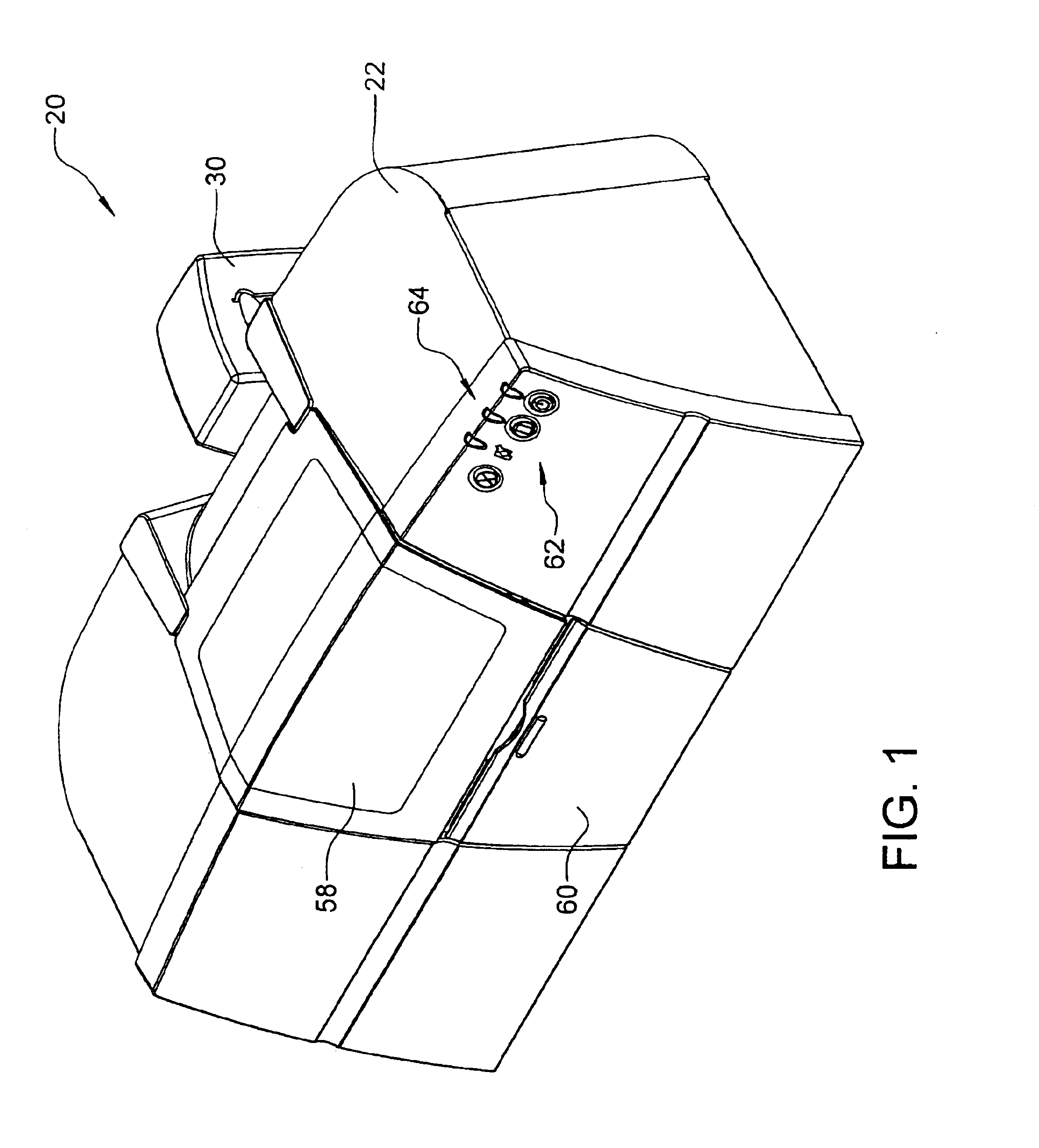
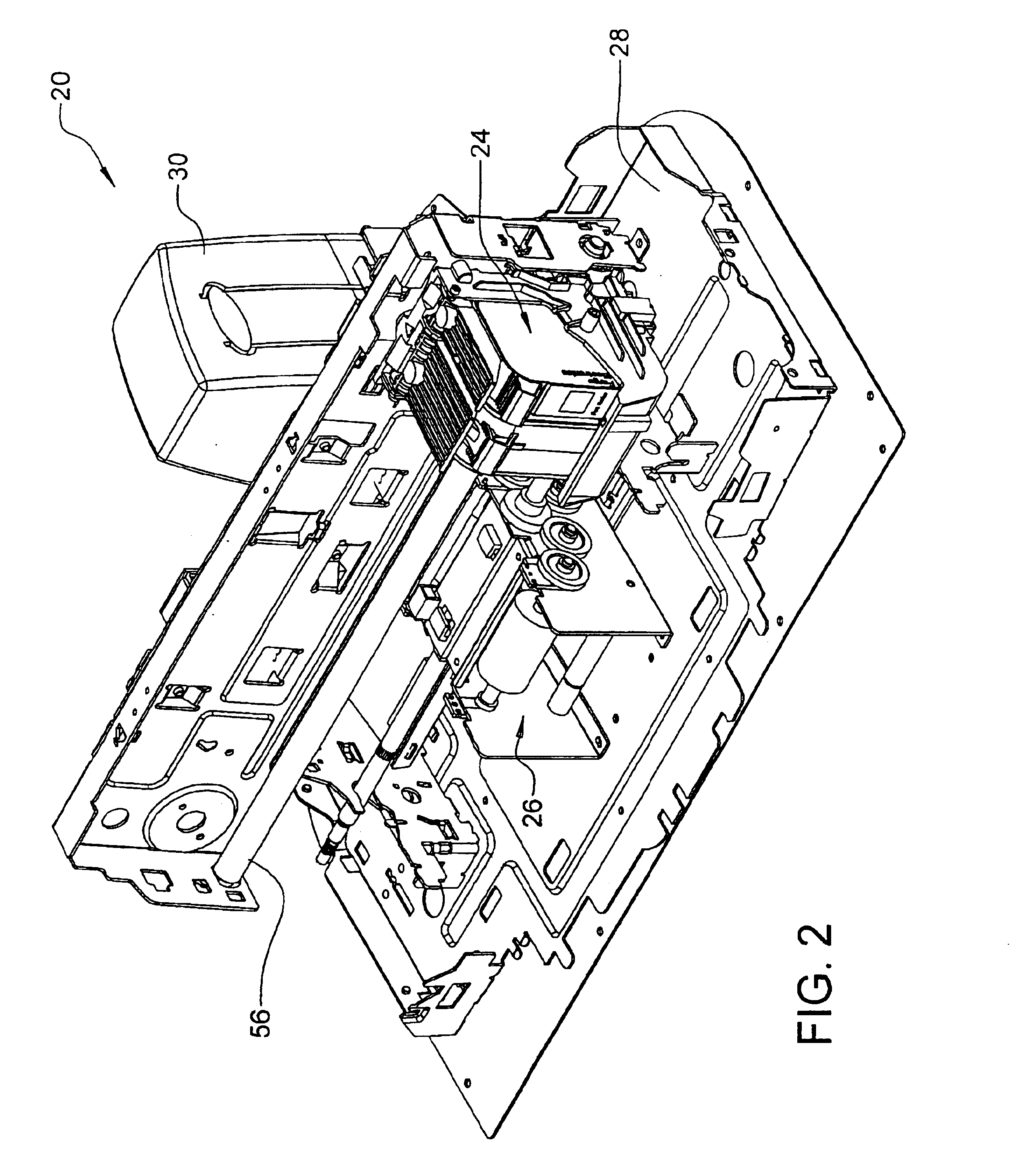
[0016]FIGS. 1 and 2 are perspective views of an example of an identification card printer 20 respectively with and without a cover 22, with which embodiments of the present invention can be used. Printer 20 generally includes a print mechanism 24, a transport mechanism 26, a base 28, and printer electronics (not shown) that control the operation of the components of printer 20. Printer 20 can receive cards for processing from card cartridge 30 of the present invention, embodiments of which will be discussed in greater detail below.
[0017]Transport mechanism 26 is adapted to deliver cards from card cartridge 30 along a print path to print mechanism 24 for printing. FIG. 3 shows a perspective view of transport mechanism 26 with card cartridge 30 lifted off a cartridge receiver 32, to which it is mounted for operation with identification card printer 20. Transport mechanism 26 includes a plurality of feed rollers 34 and guide rollers 36, some of which are driven by a motor (not shown). ...
PUM
Abstract
A card cartridge includes a housing having a pair of opposing side walls, a top, a front wall, a back wall opposite the front wall, and a base. The housing includes an interior cavity that is sized to accommodate a stack of cards, a card access, and a card output slot. The card access allows a card transport mechanism to engage a lead card contained in the housing and feed the lead card through the card output slot.
Description
CROSS REFERENCE TO RELATED APPLICATIONS[0001]The present invention is a Continuation-in-Part of U.S. patent application Ser. No. 10 / 071,554 entitled “METHOD AND APPARATUS FOR COMMUNICATING BETWEEN PRINTER AND CARD SUPPLY,” for inventors Gary M. Klinefelter, Jeffrey D. Upin, Gary A. Lenz, Martin A. Pribula and James R. Meier filed Feb. 8, 2002 now U.S. Pat. No. 6,694,884, which is a Continuation-in-Part of U.S. application Ser. No. 09 / 489,591, Filed Jan. 21, 2000, and entitled “METHOD AND APPARATUS FOR COMMUNICATING BETWEEN PRINTER OR LAMINATOR AND SUPPLIES,” which in turn claims priority to U.S. Provisional Application Ser. No. 60 / 117,123, which was filed Jan. 25, 1999; and U.S. patent application Ser. No. 09 / 967,501, entitled “CARD HOPPER,” filed Sep. 28, 2001. Additionally, reference is hereby made to the following related co-pending applications filed on even date herewith: application Ser. No. 10 / 126,428, entitled “IDENTIFICATION CARD PRINTER HAVING MULTIPLE CONTROLLERS,” for in...
Claims
Application Information
Patent Timeline
Application Date:The date an application was filed.
Publication Date:The date a patent or application was officially published.
First Publication Date:The earliest publication date of a patent with the same application number.
Issue Date:Publication date of the patent grant document.
PCT Entry Date:The Entry date of PCT National Phase.
Estimated Expiry Date:The statutory expiry date of a patent right according to the Patent Law, and it is the longest term of protection that the patent right can achieve without the termination of the patent right due to other reasons(Term extension factor has been taken into account ).
Invalid Date:Actual expiry date is based on effective date or publication date of legal transaction data of invalid patent.