Temperature compensated T-RAM memory device and method

a memory device and temperature compensation technology, applied in pulse generators, pulse techniques, instruments, etc., can solve the problems of excessive power consumption, and large sram memory cells

Inactive Publication Date: 2005-08-23
MICRON TECH INC
View PDF27 Cites 46 Cited by
  • Summary
  • Abstract
  • Description
  • Claims
  • Application Information

AI Technical Summary

Problems solved by technology

As a result, SRAM memory cells are relatively large, and they can consume a significant amount of power.
However, if the current I is maintained at a level significantly above the holding current IH, excess power is consumed, particularly in a high-capacity SRAM containing millions...

Method used


Image

  • Temperature compensated T-RAM memory device and method
  • Temperature compensated T-RAM memory device and method
  • Temperature compensated T-RAM memory device and method

Examples


Embodiment Construction

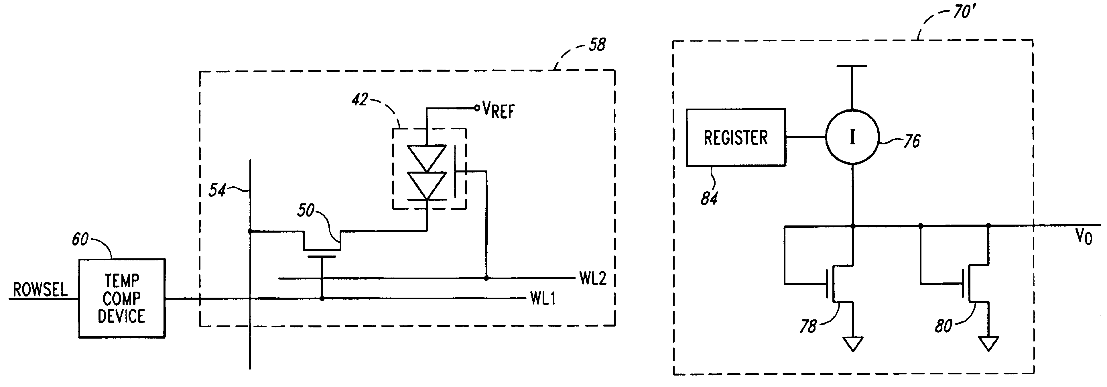
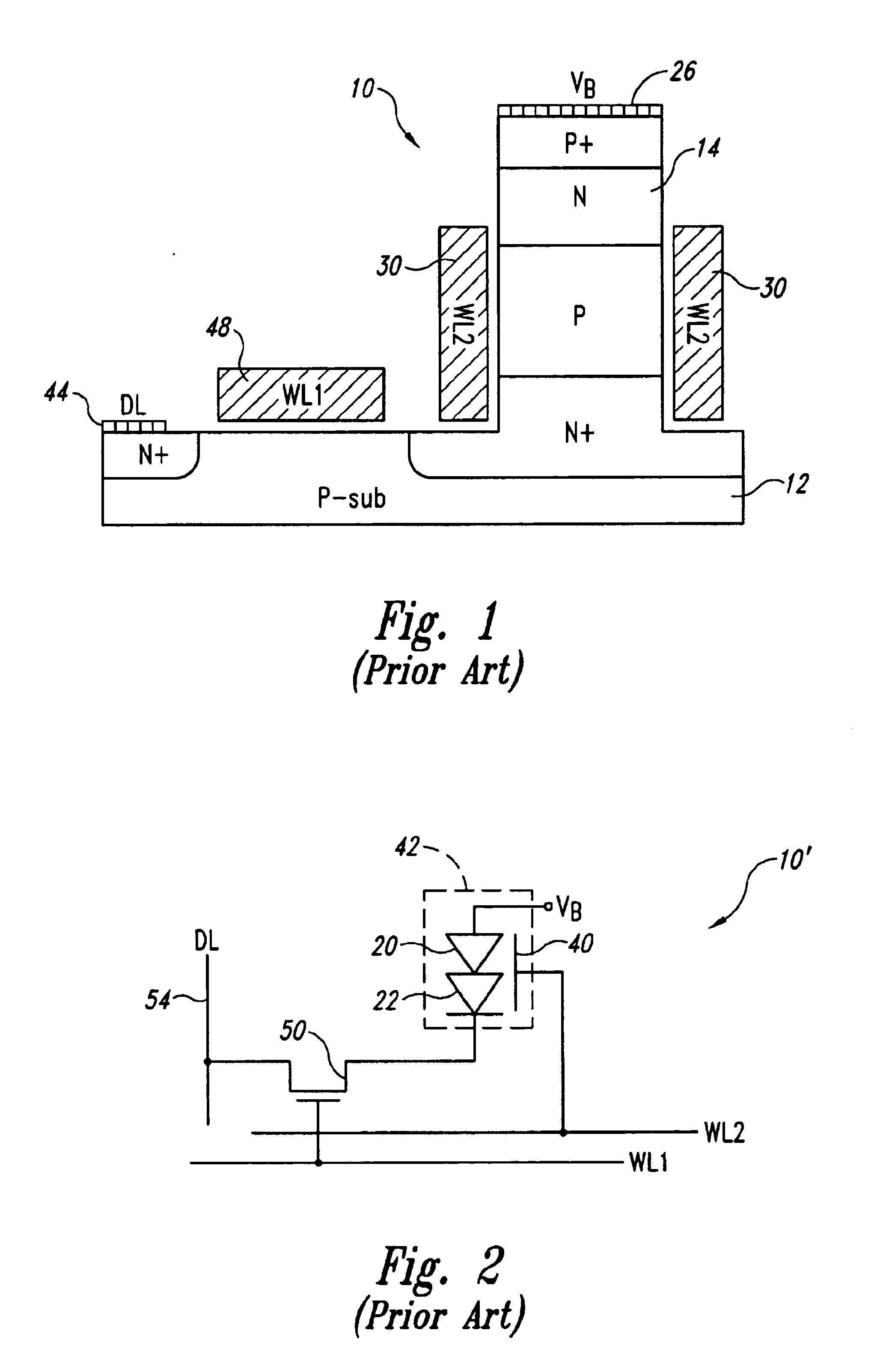
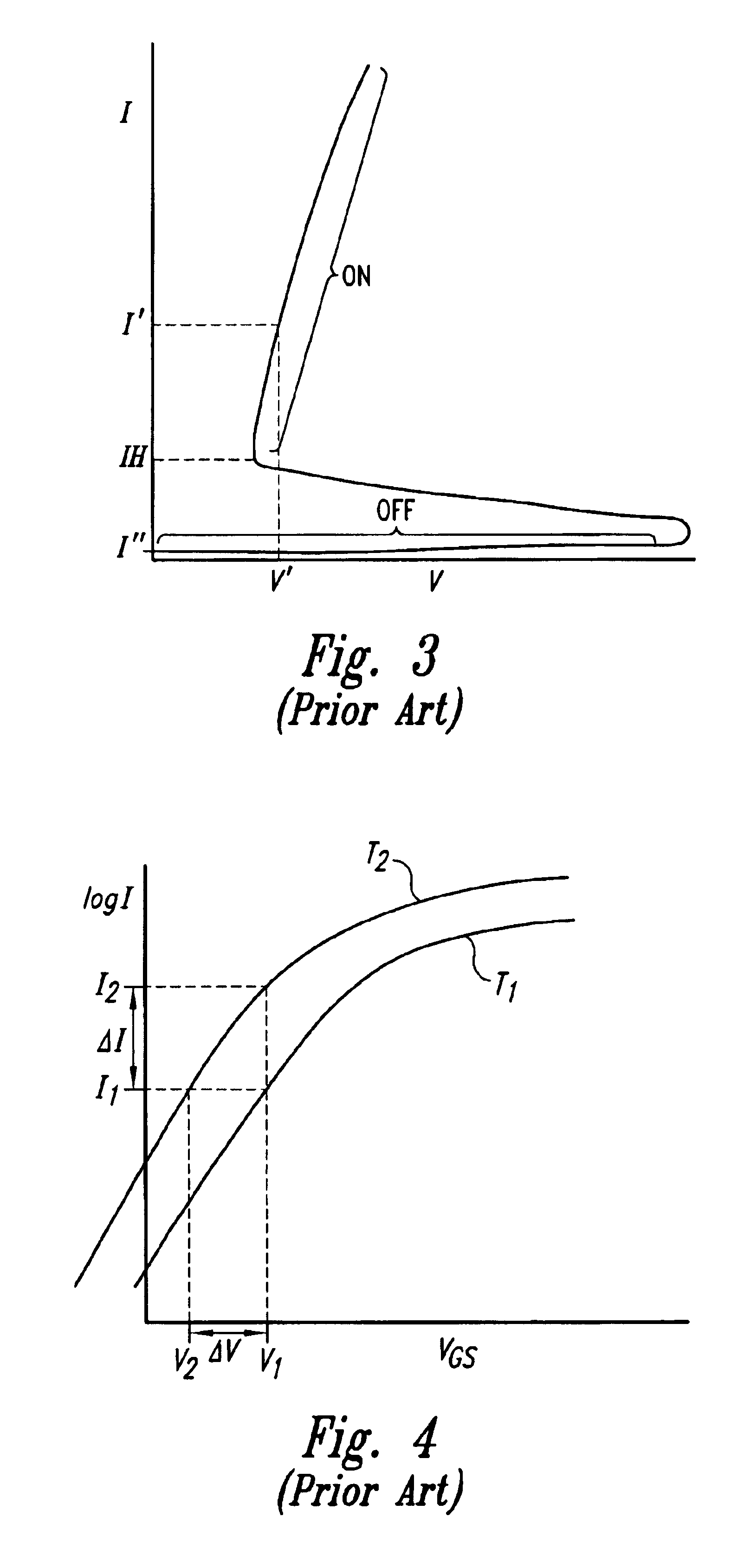
[0026]The principle of operation of the disclosed embodiments of the invention can best be explained with further reference to FIGS. 2-4. It will be recalled from the previous explanation of FIG. 3 that data loss in a T-RAM memory cell can be prevented by maintaining the sub-threshold current of the access transistor 50 (FIG. 2) at a constant level slightly above the holding current IH despite variations in temperature. With reference to FIG. 4, the sub-threshold current can be maintained at a constant level, for example I1, by reducing the gate-to-source voltage from V1 to V2 as the temperature rises from T1 to T2. More specifically, the gate-to-source voltage is set to V1 at the relatively low temperature T1 to provides a sub-threshold current of I1. The gate-to-source voltage is then reduced to V2 to maintain the same sub-threshold current I1 when the temperature increases to T2. Thus, the gate-to-source voltage varies over a range ΔV to maintain a constant sub threshold current ...


PUM


Abstract

A T-RAM memory cell includes a temperature compensation device to adjust the gate-to-source voltage of an access transistor for the memory cell as a function of temperature so that the sub-threshold current of the transistor is insensitive to temperature variations. As a result, the sub-threshold current can be maintained slightly above the holding current of a thyristor used in the memory cell despite substantial temperature variations. In one embodiment, the temperature compensation device includes a current source directing a fixed current through a diode-connected transistor of the type used as the memory cell access transistor. Temperature induced changes in a reference voltage generated at the junction between the current source and the transistor therefore match the temperature induced changed in the sub-threshold current of the access transistor. As a result, the sub-threshold current of the access transistor can be made insensitive to temperature variations by applying the reference voltage to the gate or source of the access transistor.

Description

CROSS-REFERENCE TO RELATED APPLICATION[0001]This application a divisional of pending U.S. patent application Ser. No. 10 / 165,665, filed Jun. 6, 2002 now U.S. Pat. No. 6,781,907.TECHNICAL FIELD[0002]The invention relates to memory devices, and, more particularly, to a memory device using T-RAM (thyristor-based SRAM) memory cells.BACKGROUND OF THE INVENTION[0003]Static random access memories (“SRAMs”) have traditionally been implemented using memory cells formed by cross-coupled MOSFET transistors. Each memory cell is coupled to a pair of complementary digit lines by respective access transistors. Thus, each memory cell requires 4 transistors. As a result, SRAM memory cells are relatively large, and they can consume a significant amount of power. Attempts have therefore been made to devise alternative means for implementing SRAM memory cells.[0004]One approach to improving upon existing SRAM memory cell technology is the use of a thyristor as a data storage device. Thyristor-based SRA...

Claims


Application Information

Patent Timeline
IPC IPC(8): G11C7/04G11C11/00G11C17/06G11C11/36G11C11/39
CPCG11C11/39
Inventor MARR, KEN W.
Owner MICRON TECH INC
Why Eureka
Try Eureka