
System and method for monitoring a security state of an electronic device

Inactive Publication Date: 2005-08-23
QUALCOMM INC
View PDF125 Cites 81 Cited by
  • Summary
  • Abstract
  • Description
  • Claims
  • Application Information

AI Technical Summary

Benefits of technology

[0011]The monitoring system presented in the exemplary embodiments may have numerous advantages. First, a monitoring system using physical or electrical characteristics of a PED as a mechanism for defining a security state provides a level of security against criminals or others who may mimic the device in order to access a user's financial account (e.g., by copying software programs from the device). For example, the present system may make it more difficult for a criminal to access a user's financial account while the PED is in a closed security state. Additionally, by using existing hardware and software (e.g., hardware pieces or software applications on the PED) for determining a security state, few additional resources may be needed for creating the monitoring system, and it may be implemented at minimal additional cost. Also, such a system may intuitively bring the security state of the PED under the direct manipulation and supervision of the user. Furthermore, the present monitoring system may also be conveniently combined with a number of identification mechanisms (e.g., personal identification numbers (PINs), serial numbers, fingerprint analysis, passwords, etc.) for a better and more effective monitoring system.

Problems solved by technology

Unfortunately, current methods and systems for use in a financial transaction still leave the process an undesirable one.
Although credit cards may provide advantages over cash, they do not provide an optimum solution.
Carrying multiple cards is often bulky and cumbersome, which is both inconvenient and undesirable to the person carrying them.
This leaves the authorized user and their credit vulnerable to thieves or others who might use that information wrongly.
Additionally, a criminal may use another card to mimic a user's credit card and steal a user's identity.
Thus, credit cards may be problematic when attempting to identify and authenticate a user.
However, current smart cards and super smart cards still retain many of the drawbacks of traditional credit cards.
Similar to credit cards, smart cards may not allow remote exchange of information, and although contactless cards have been developed, each contactless card may still require the user to position the card near the card reader.
In addition, due to their standard credit-card size, smart cards and super smart cards also lack feature-rich functionality and are therefore limited to few functions.
Such limited functionality presents an undesirable solution, as smart cards and super smart cards cannot conveniently replace other electronic devices to provide additional functionality, such as Internet access, email access, organizational programs (e.g., address book, appointment calendars, etc.), database programs, video games, and the like.
However, such devices, as well as credit cards, smart cards, and super smart cards, may face difficulties when attempting to identify a user device (e.g., portable electronic device or card).
For example, due to copying of software programs, current user devices may be unable to identify an original copy of a software program and the user device for which the program was intended.
Standard authentication mechanisms, such as using a user's signature or serial number identification, may not provide enough security from the most daring and capable criminals.
For example, the present system may make it more difficult for a criminal to access a user's financial account while the PED is in a closed security state.
Also, such a system may intuitively bring the security state of the PED under the direct manipulation and supervision of the user.

Method used


Image

  • System and method for monitoring a security state of an electronic device
  • System and method for monitoring a security state of an electronic device
  • System and method for monitoring a security state of an electronic device

Examples


Embodiment Construction

I. Monitoring Security States of a Personal Digital Assistant

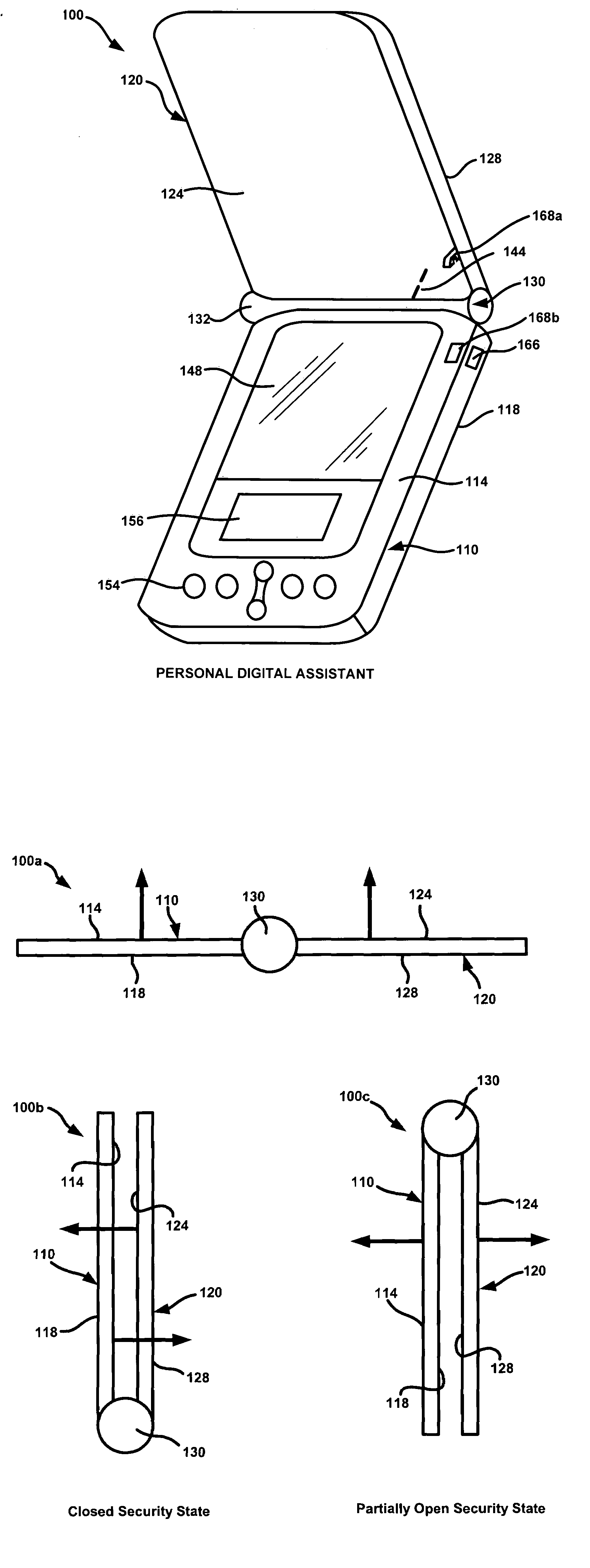
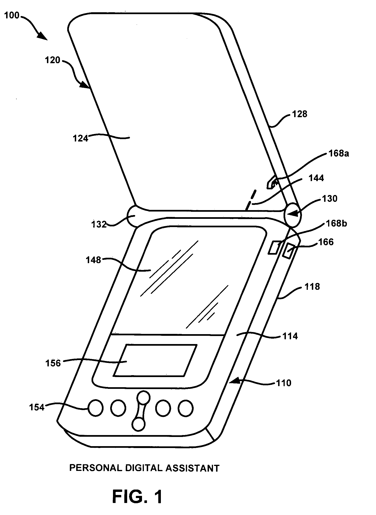
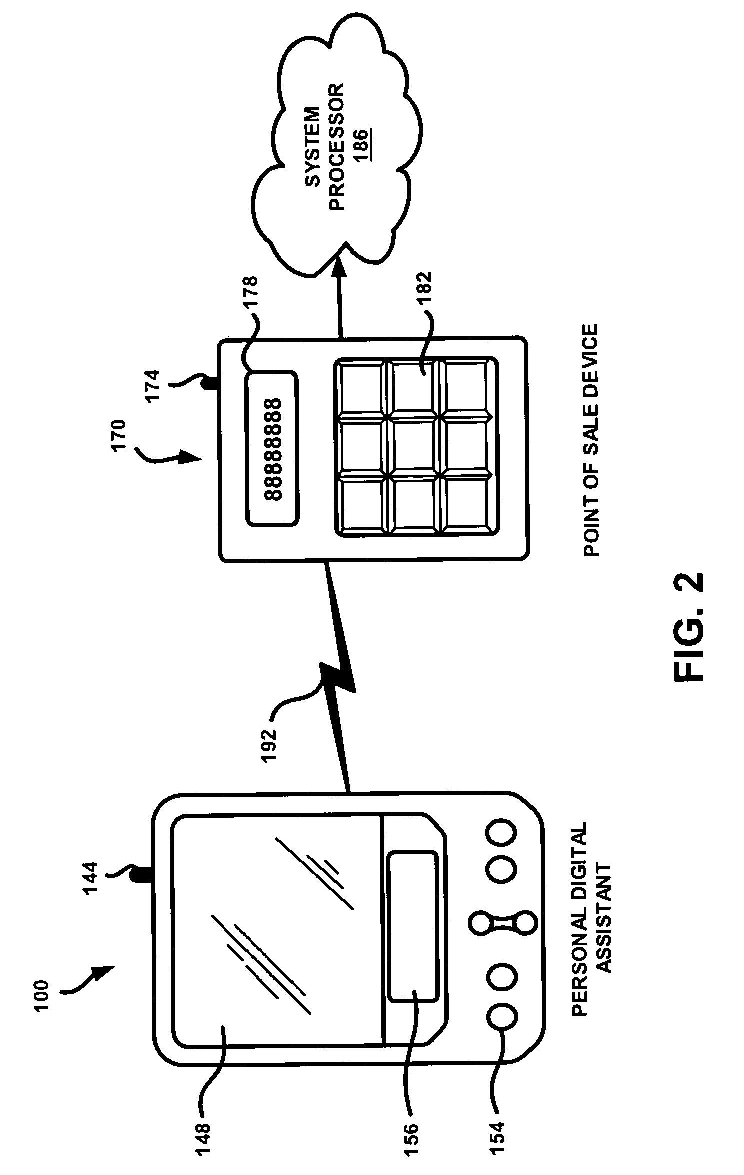
[0021]In an exemplary embodiment, a user utilizes a portable electronic device, such as a personal digital assistant (PDA), to engage in a financial transaction with a transactional terminal, such as a point-of-sale device (POS). Before such a transaction can take place, it may be beneficial to verify that a valid PDA is being utilized. This may be accomplished by monitoring a security state of a PDA, which may be based on certain physical characteristics of the device. In an exemplary scenario, the relative position of a first piece (e.g., base) and a second piece (e.g., lid) of the PDA may be detected by a sensor and used to determine a security state. For example, if the second piece is covering the first piece, the PDA will generally not be in use, and a financial transaction between the PDA and a transactional terminal may be restricted. This type of security state may be called a “closed security state”. Similarly, a...


PUM


Abstract

A system and method for monitoring a security state of a portable electronic device (PED), such as a personal digital assistant (PDA), are provided. A security state may be determined by physical or electronic characteristics of the PED. The relative position of PED pieces, the position of a latch, and / or the status of a software application may determine a security state. Furthermore, a PED may have open, closed, and partially open security states. Information about a current security state of a PED may be transmitted to a point-of-sale device (POS), system processor, and / or financial institution. The PED or any of these other devices may use this information to determine whether to allow or restrict a financial transaction involving the PED. Additionally, a software program on the PED may be allowed or restricted from running depending on the information about the current security state.

Description

FIELD OF THE INVENTION[0001]The present invention pertains to a system and method for monitoring a security state of a portable electronic device, such as a personal digital assistant.BACKGROUND OF THE INVENTION[0002]Millions of financial transactions occur every day across the globe. A large portion of these financial transactions, occurring in the form of a cash or credit card purchase, involve an exchange of products or services for money. For example, a financial transaction might include purchasing one or more products such as the latest designer wear, or the newest compact disk recording, or simply buying a hotdog at the local food stand. Other times a financial transaction might include purchasing a service such as dry cleaning, taxi transportation, or a car wash. Of course, these examples provide just a few types of products or services available, but one can imagine the number of financial transactions involving products or services that occur every day. Furthermore, there ...

Claims


Application Information

Patent Timeline
IPC IPC(8): G06F15/00G06Q20/00
CPCG06Q20/20G06Q20/32G06Q20/3227G06Q20/327G06Q20/403G06Q20/382
Inventor WEBB, RUSSBLIGHT, DAVID
Owner QUALCOMM INC
Learn More