
Port expansion peripheral module system

a peripheral module and port expansion technology, applied in the field of port expansion systems, can solve the problems of not incorporating traditional, standard interfaces on the pc, and achieve the effect of sufficient structural integrity and easy manual separation of the modules

Inactive Publication Date: 2005-08-23
INTEL CORP
View PDF40 Cites 70 Cited by
  • Summary
  • Abstract
  • Description
  • Claims
  • Application Information

AI Technical Summary

Benefits of technology

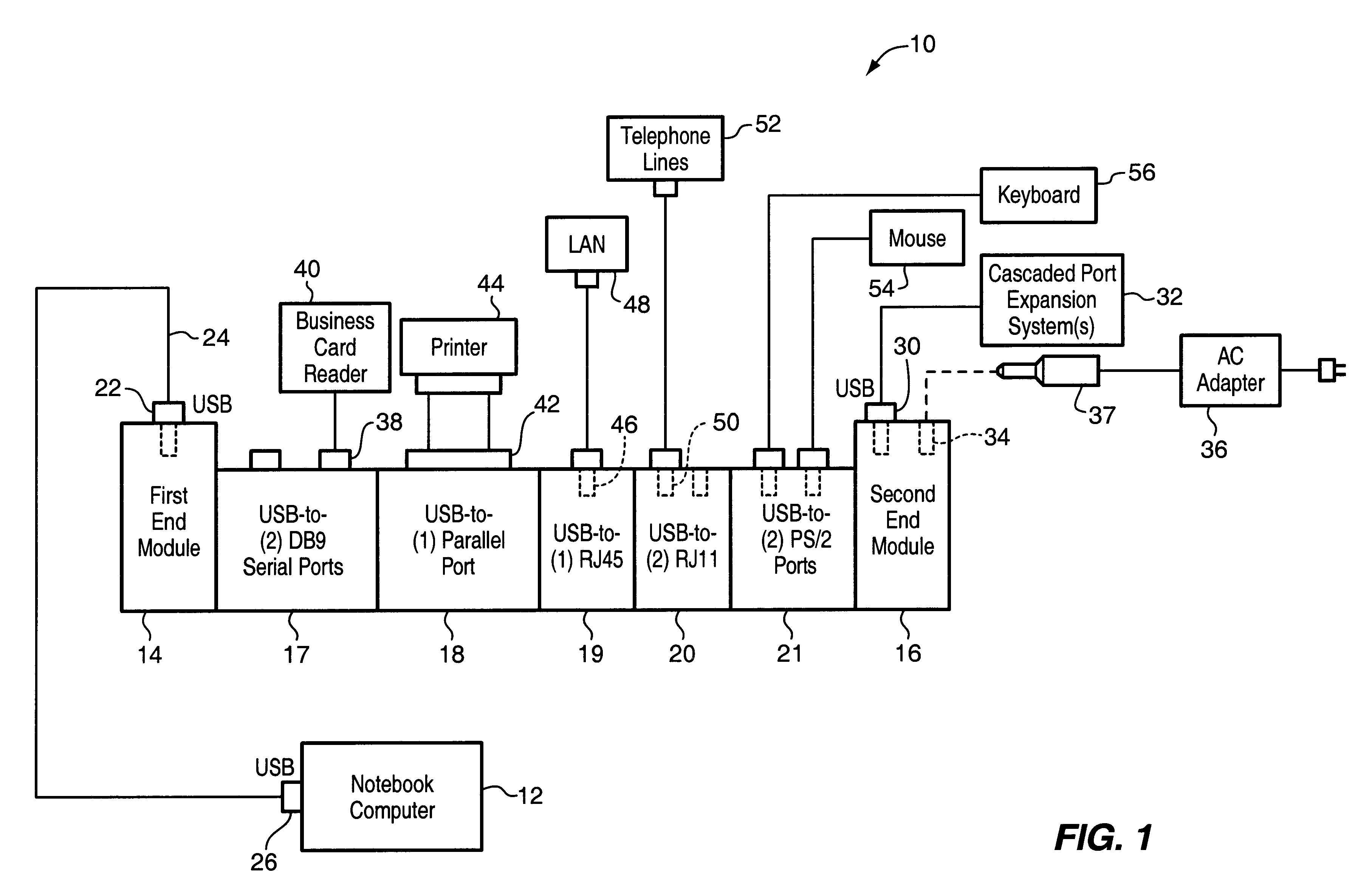
[0010]The invention further provides for the releasable or detachable coupling of the various peripheral device modules. Thus, the user can easily connect and separate the modules manually to readily custom design and assemble any desired combination and number of peripheral device modules within the limits of the host port specification. The mechanical coupling between adjacent modules includes mating connectors which also serve to transmit the required electrical signals between the individual device modules of the port expansion system and between the port expansion system and the host system thereby eliminating the need for external hubs and individual cables to the various modules. A technique for passing signals between the peripheral device modules allow the peripheral device modules to be connected together in any sequence, thus allowing a user to custom-configure a port expansion system to the user's individual requirements. In addition, the system can be disassembled and the peripheral device modules reassembled in a different order if desired. By making available a variety of individual peripheral device modules, a user can purchase and add such modules to an existing system in building block fashion to mix and match peripherals and network connections.
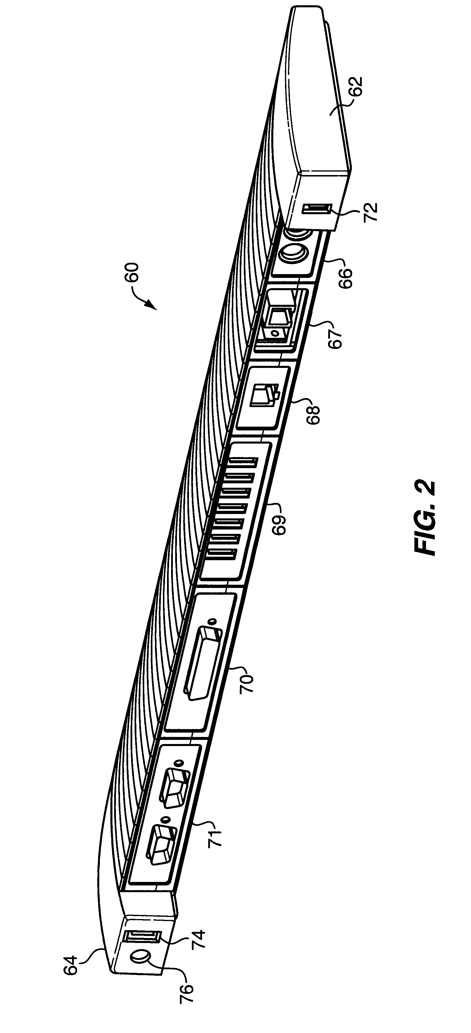
[0014]In accordance with a preferred embodiment, the port expansion system of the present invention utilizes standard, mateable DB-25 connectors for providing electrical and mechanical coupling between adjacent modules. Although the mechanical interconnection between adjacent modules afforded by the mateable DB-25 connectors provides sufficient structural integrity, such mechanical joinder of adjacent modules is preferably supplemented by means for releasably latching the modules together. The combination of the mechanical interconnection provided by the DB-25 connectors and the latching means results in a structure that has the rigidity and sturdiness approaching that of an integral or one piece unit, and creates the appearance of a one piece or solid block construction, yet nevertheless permits easy manual separation of the modules.

Problems solved by technology

Such PCs do not incorporate traditional, standard interfaces.

Method used


Image

  • Port expansion peripheral module system
  • Port expansion peripheral module system
  • Port expansion peripheral module system

Examples


Embodiment Construction

[0038]The following detailed description is only illustrative of the invention. Various alternatives and modifications can be devised by those skilled in the art without departing from the spirit of the invention. For example, although the invention will be described specifically for use with the USB standard bus interface or protocol, it will be evident to those skilled in the art that the invention has applicability to other standard bus interfaces such as IEEE 1394, also called “Firewire” or “i.Link”, and SCSI. Accordingly, the invention is intended to embrace all alternatives, modifications and variations as fall within the scope of the appended claims.

[0039]FIG. 1 shows in block diagram form a port expansion system 10 in accordance with a first specific, exemplary embodiment of the invention, for attaching a variety of computer peripheral devices to a host system 12 which, in the example shown, is in the form of a notebook computer. As used herein, the term “peripheral device” ...


PUM


Abstract

A user configurable, modular port expansion system allows the user of a host system such as a USB-enabled personal computer to customize a desired configuration of one or more peripheral device modules without the use of cables between modules. The peripheral device modules are physically and electrically connectable to each other side-by-side between a hub end module and a power end module in any sequence so that there can be provided, within the limits of the host port specification, virtually any number of selected, expanded functions in any combination. The peripheral device modules may include, by way of example, a standard parallel DB-25 port module, a two-port serial PS / 2 module, a two-port serial DB-9 module, a four- or seven-port USB hub, an RJ-11 Ethernet LAN module, and an RJ-11 modem module. Where the host port is USB compliant, power to the peripheral device modules may be supplied by the host system via a USB standard cable connected to the USB port of the hub end module, or, if more power is required, by an external a.c. power adapter connectable to the power end module. The power end module may also include an USB expansion port.

Description

CROSS-REFERENCE TO RELATED APPLICATION[0001]This application is a continuation of U.S. patent application Ser. No. 09 / 569,855, entitled “Computer Port Expansion”, filed May 12, 2000, issued as U.S. Pat. No. 6,697,892 on Feb. 24, 2004, which in turn claims the benefit of provisional application Ser. No. 60 / 142,733 filed Jul. 8, 1999.BACKGROUND OF THE INVENTION[0002]1. Field of the Invention[0003]The present invention relates generally to a port expansion system for connecting a single port, such as a USB port, on a host system such as a personal computer (PC) to various computer peripheral devices and functions, and particularly to such an expansion system that is user configurable so as to provide a high degree of flexibility and efficiency in the connection of the host system to a wide selection of peripheral devices and functions.[0004]2. Description of the Prior Art[0005]Although the invention and its background will be described chiefly in the context of the USB standard bus int...

Claims


Application Information

Patent Timeline
Patent Type & Authority Patents(United States)
IPC IPC(8): G06F13/38G06F13/40G06F13/12G06F3/00
CPCG06F13/385G06F13/4095G06F2213/4002
Inventor LAITY, IAN A.THORNTON, TIMOTHY J.GU, GEORGE Q.
Owner INTEL CORP
Learn More