
Undercutter for a shaving apparatus

a shaving apparatus and undercutter technology, applied in the field of shaving apparatus, can solve the problems of unsatisfactory shaving, unbalanced blade blockage, dusty debris, etc., and achieve the effect of smooth shaving skin and improved closeness

Inactive Publication Date: 2005-08-30
BRAUN GMBH
View PDF14 Cites 4 Cited by
  • Summary
  • Abstract
  • Description
  • Claims
  • Application Information

AI Technical Summary

Benefits of technology

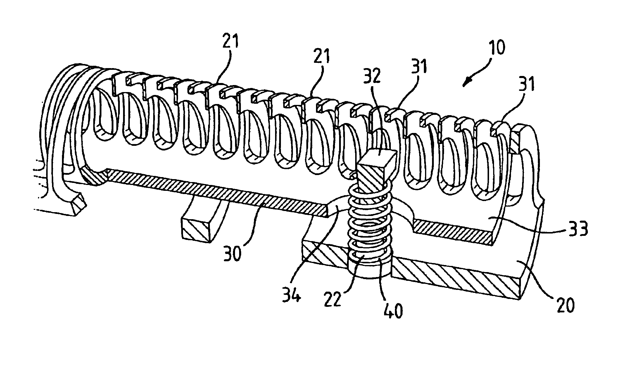
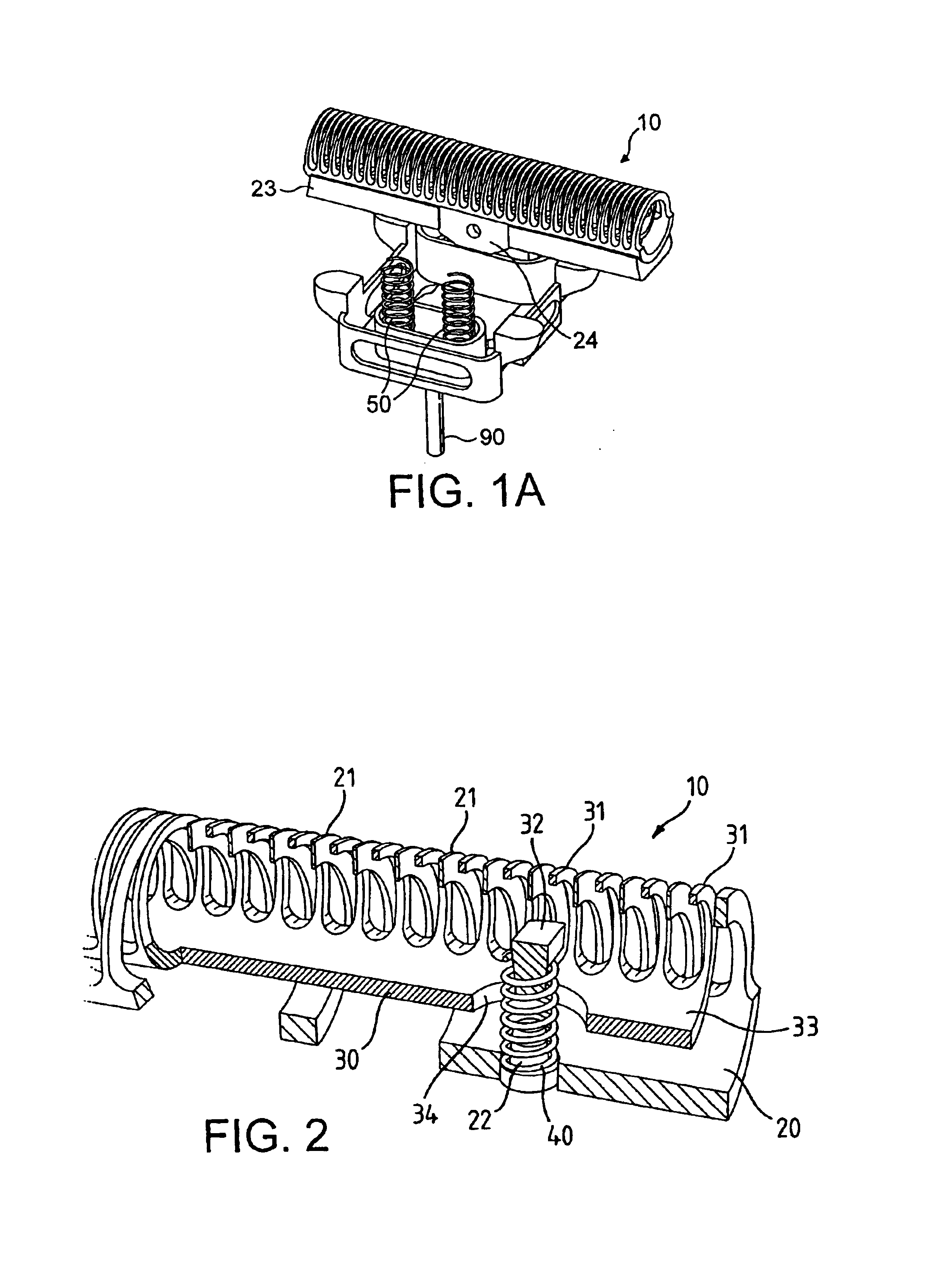
The invention is a shaving apparatus that improves cutting efficiency by increasing the number of cutting events without increasing the speed of the drive motor. It includes an outer cutter, an undercutter assembly, and a motor for moving the undercutter assembly in a reciprocation direction. The undercutter assembly consists of a primary undercutter and a secondary undercutter that are interleaved. The secondary undercutter is nested within the primary undercutter and is movable relative to it. The invention also includes a method of shaving by reciprocally moving the undercutter assembly in contact with the outer cutter, trapping hairs between the interleaved blade elements of the primary and secondary undercutters, and pulling and cutting the trapped hairs. The use of the secondary undercutter allows for improved shaving closeness and a smooth shaved skin.

Problems solved by technology

Conventional powered shaving devices typically cut individual hairs into a plurality of small pieces, leading to a dusty debris.
Further, the resulting shaved skin may comprise stubble hairs which have not been cut in a fully satisfactory way.
The blade block includes weights to cause the blade block to be unbalanced and to vibrate and move particularly in a lateral direction, which in turn causes vibration of the housing and of the foil.
However, conventional shaving apparatus often leaves stubble hair of a significant length in the shaved skin so that the user appears to be unshaved after a short period of time.

Method used


Image

  • Undercutter for a shaving apparatus
  • Undercutter for a shaving apparatus
  • Undercutter for a shaving apparatus

Examples


Embodiment Construction

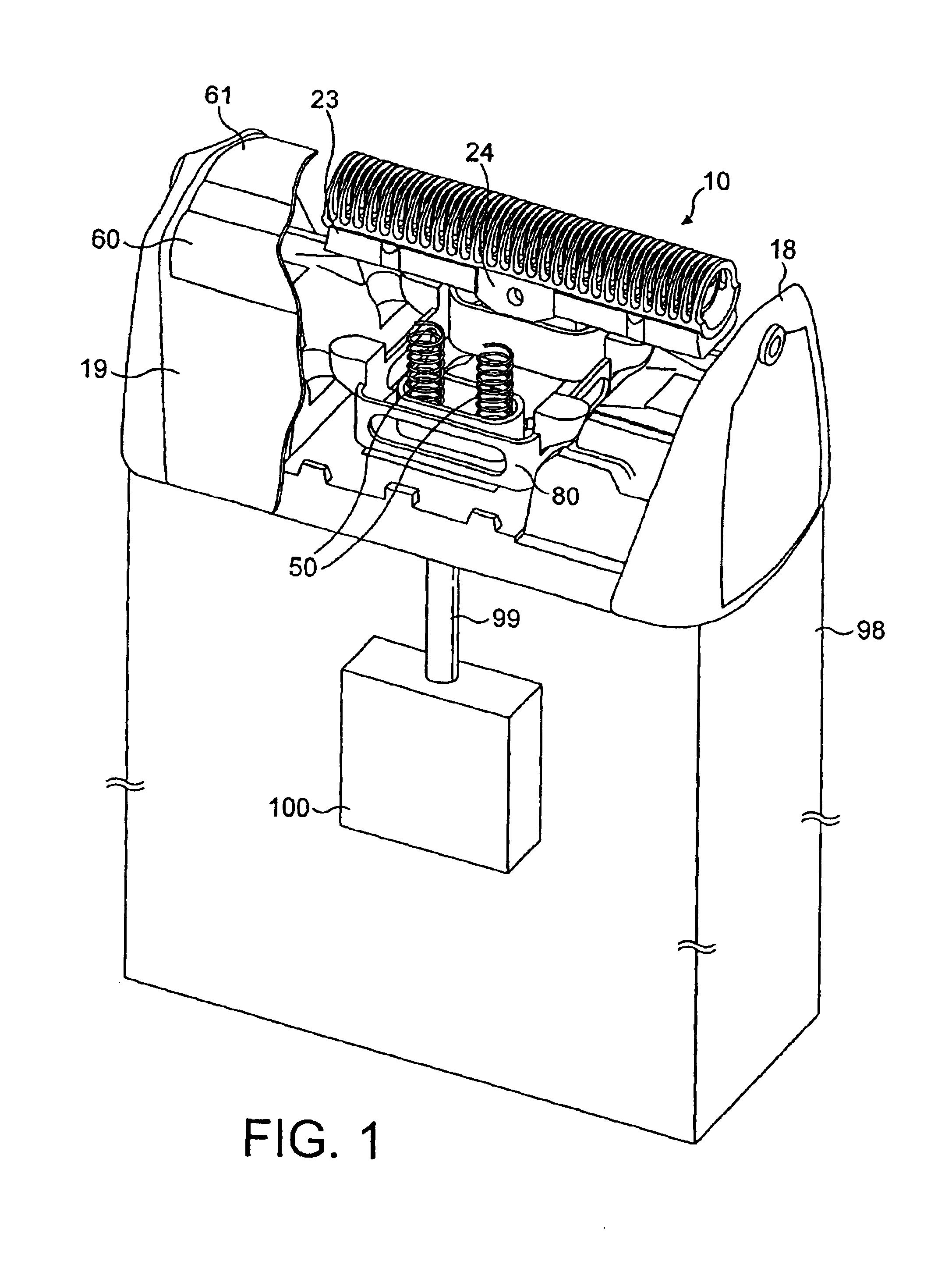
[0041]FIG. 1 shows a shaver having a shaver head of the type having two cutter units, each having a respective undercutter assembly and an outer cutter or foil. For clarity, FIG. 1 shows only a scrap view of the outer cutters 60, 61 (which are conventional) mounted in a foil frame 19. A first undercutter assembly 10 is shown complete in its assembled condition. Only part of the second undercutter assembly is shown.

[0042]Each undercutter assembly such as 10 comprises a primary cutter, a secondary cutter, a support block 23, and a sub-mounting 80 which carries a spring 50, preferably at least two springs 50, as illustrated in FIG. 1. For the second undercutter assembly, only the sub-mounting 80 and two springs 50 are shown. It is understood that presence of spring or springs 50 is not essential to practicing the present invention, but is preferred for better shaving efficiency. It is understood that the sub-mounting 80 is part of the drive block, which is known in the art and is conve...


PUM

PropertyMeasurementUnit
weightsaaaaaaaaaa
lengthaaaaaaaaaa
widthaaaaaaaaaa

Abstract

A shaving apparatus includes an outer cutter (60), for example in the form of a perforated foil, and an undercutter assembly (10), adjacent to the outer cutter, which is drivable for linear reciprocation in a reciprocation direction. The undercutter assembly has a driven primary undercutter (20) and a secondary undercutter (30), which is moveable with respect thereto, the blade elements of the primary and secondary undercutters being mutually interleaved. When the primary undercutter (20) is reciprocated relative the outer cutter (60), the secondary undercutter (30) also performs a reciprocating movement, which lags behind that of the primary undercutter, so the blade elements of the primary and second undercutters move towards one another at intervals and can trap hairs therebetween, causing them to be pulled in addition to the cutting action and thus achieving a closer shave.

Description

FIELD OF THE INVENTION[0001]This invention relates to shaving apparatus and to methods for shaving hair from human skin.BACKGROUND ART[0002]Implements such as razors or electric shavers for cutting or shaving hair are well known in the prior art. Most prior art shaving implements for cutting human facial hair are designed to cut hair close to skin level, and preferably beneath that level without nicking or cutting the skin.[0003]Conventional powered shaving devices typically cut individual hairs into a plurality of small pieces, leading to a dusty debris. Further, the resulting shaved skin may comprise stubble hairs which have not been cut in a fully satisfactory way.[0004]Various attempts have been made to overcome this problem. For example, an electric dry shaver is disclosed in U.S. Pat. No. 4,139,940 (Buras, Jr.) which has projections on the outer surface of the cutting foil to move and lift low lying facial hairs for cutting by underlying blades on a blade block. The blade bloc...

Claims


Application Information

Patent Timeline
Patent Type & Authority Patents(United States)
IPC IPC(8): B26B19/04B26B19/42
CPCB26B19/042B26B19/044Y10T83/04
Inventor STEVENS, CHRISTOPHER JOHN
Owner BRAUN GMBH
Learn More