

Rotational angle detecting apparatus, torque detecting apparatus and steering apparatus
- Summary
- Abstract
- Description
- Claims
- Application Information
AI Technical Summary
Benefits of technology
Problems solved by technology
Method used
Image

Examples
embodiment 1
Another Embodiment 1
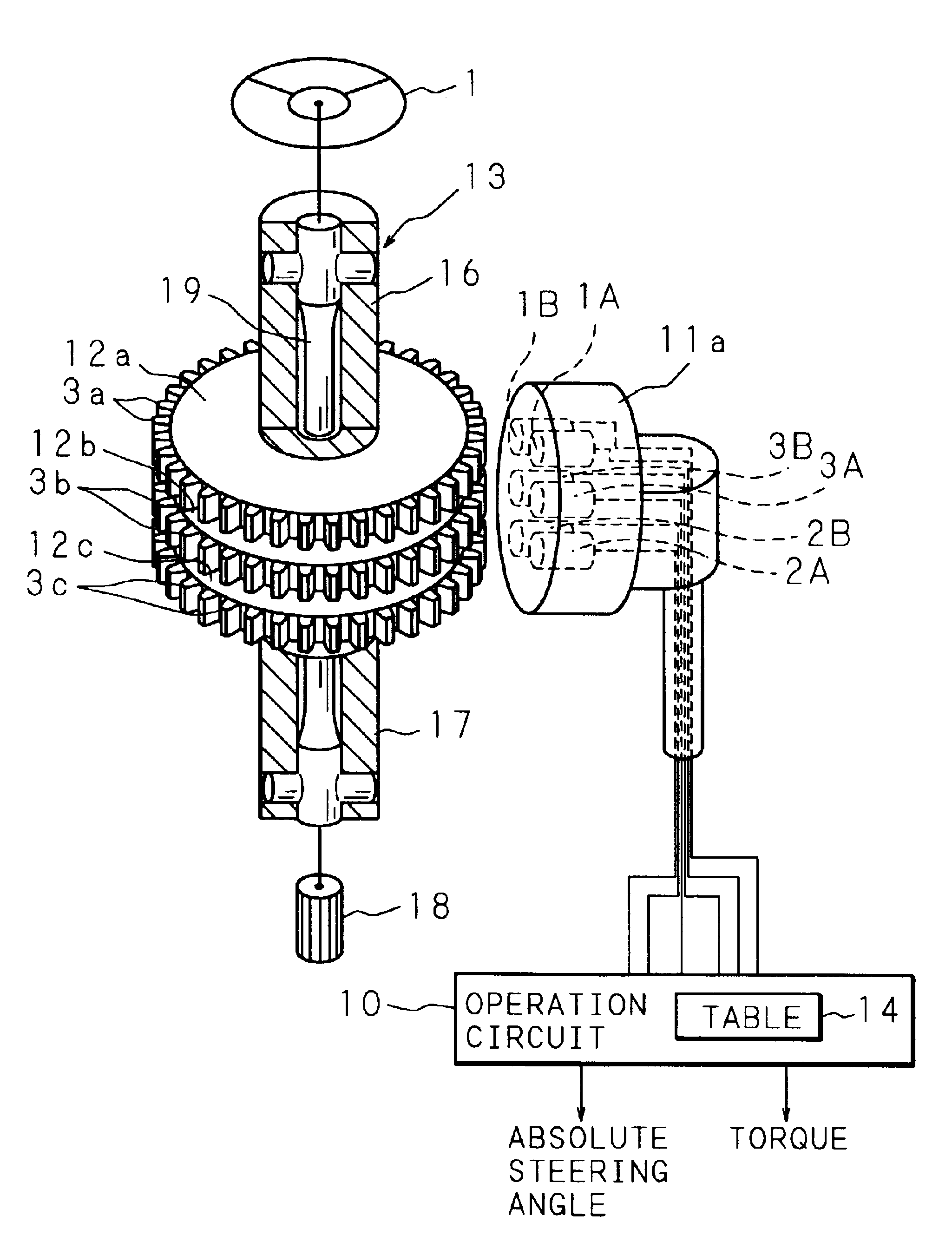
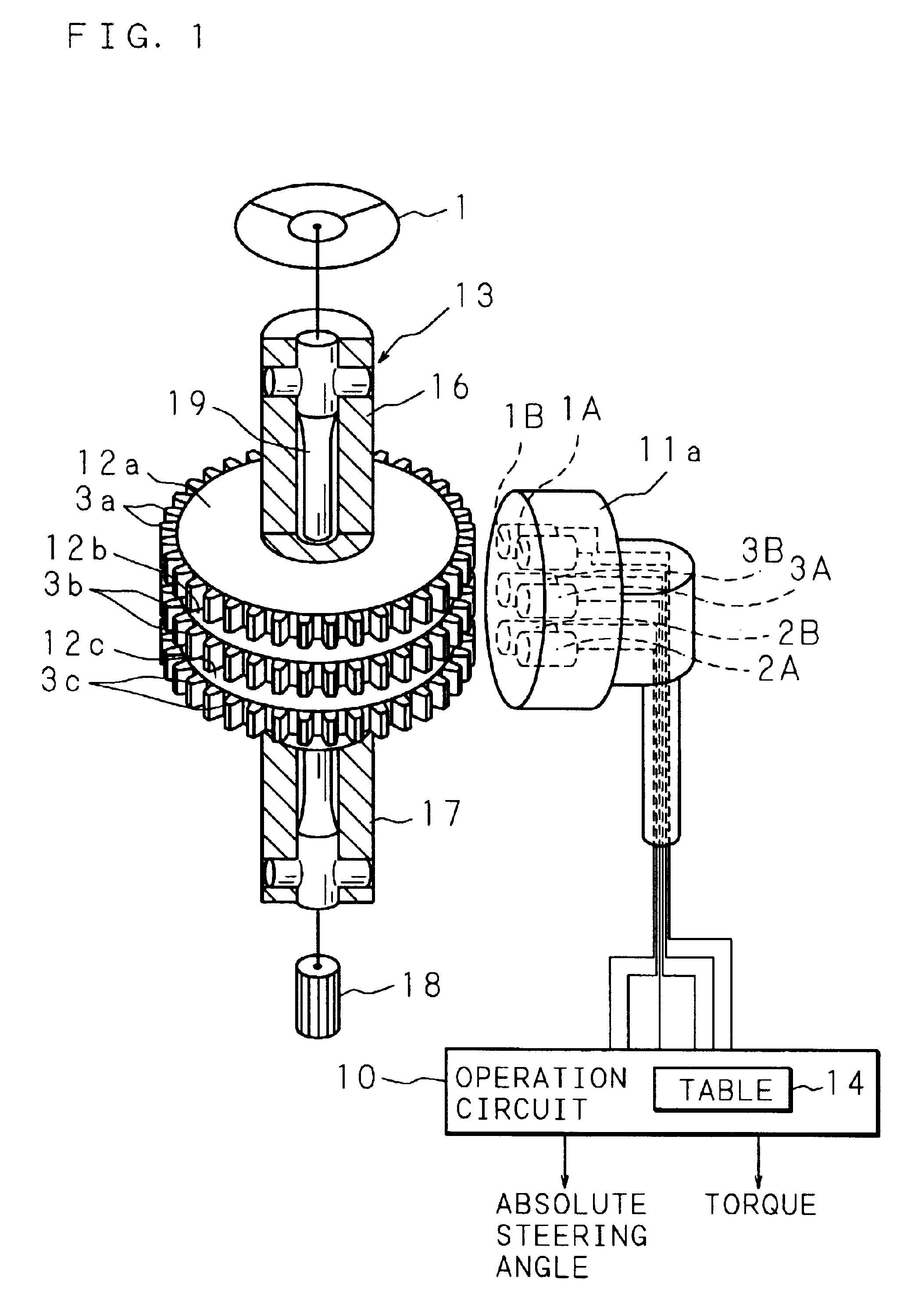
[0065]FIG. 7 is a schematic view showing the configurations of a rotational angle detecting apparatus, a torque detecting apparatus and a steering apparatus in accordance with another embodiment. In this steering apparatus, target plates 12c and 12d are fitted coaxially on the output shaft 17 of the torque detecting apparatus and the steering apparatus described in FIG. 1 and secured thereto with the target plate 12c disposed on the side of the steering wheel 1, whereby an output shaft 17a is formed. On the outer circumferential surface of the target plate 12d, a plurality of targets 3d, which are convex portions made of a magnetic material, 37 pieces for example, protrude at equal intervals in the circumferential direction.
[0066]The targets 3c of the target plate 12c on the side of the output shaft 17a and the targets 3a of the target plate 12a on the side of the input shaft 16 are aligned in the circumferential direction and provided in parallel.
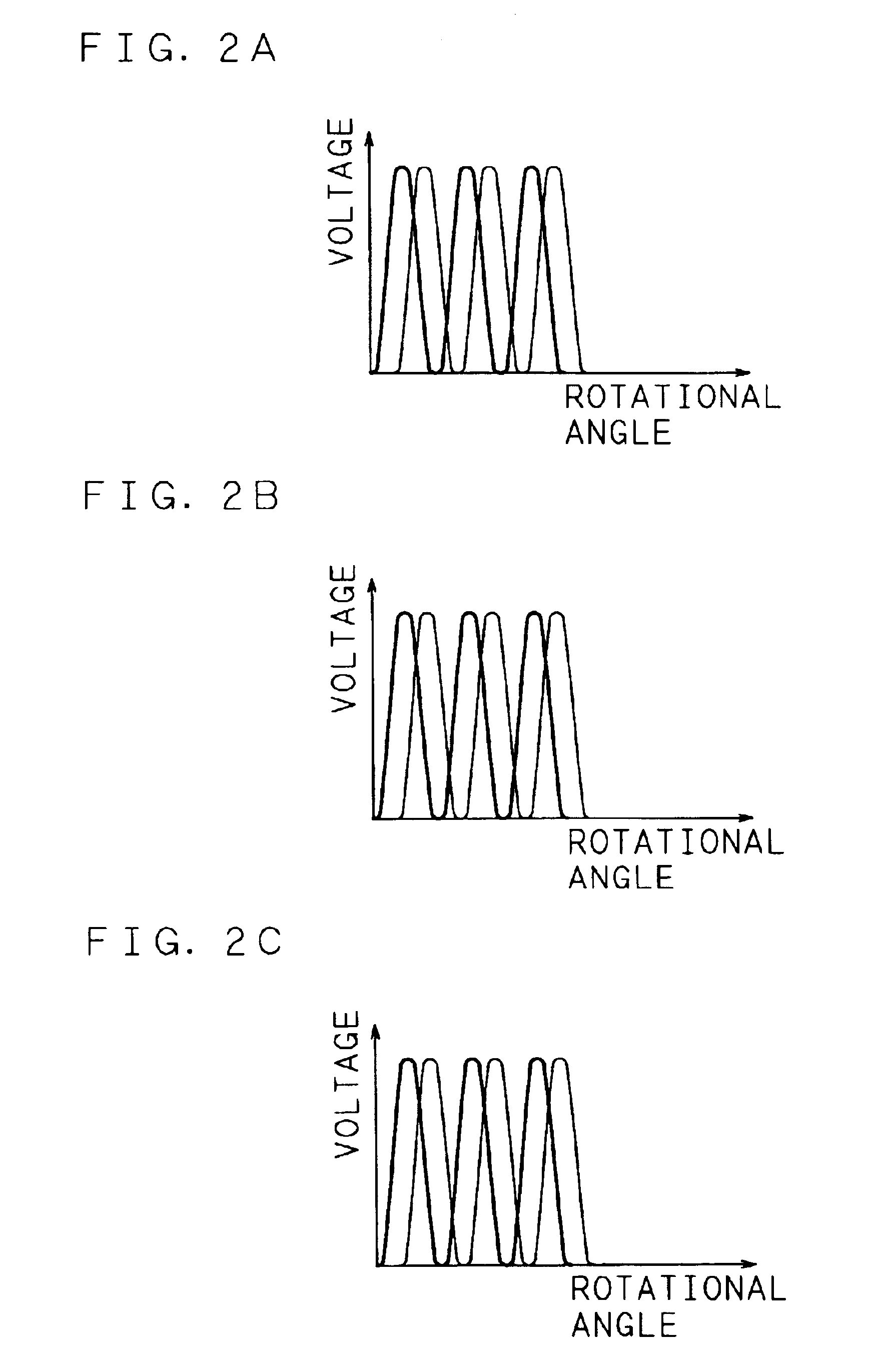
[0067]The numbe...
embodiment 2
Another Embodiment 2
[0079]FIG. 8 is a schematic view showing the configurations of a torque detecting apparatus and a steering apparatus in accordance with still another embodiment. In the torque detecting apparatus and the steering apparatus, the target plate 12b is eliminated from the input shaft 16 of the rotational angle detecting apparatus, the torque detecting apparatus and the steering apparatus described in FIG. 1, whereby an input shaft 16a is formed.
[0080]Outside the target plates 12a and 12c, a sensor box 11 is disposed so as to face the outer fringes of the targets 3a and 3c on the outer circumferences of the target plates 12a and 12c, respectively. The sensor box 11 is secured to and supported by a stationary portion, such as a housing, for rotatably supporting the input shaft 16a and the output shaft 17. The magnetic sensors 1A and 1B disposed at different positions opposite to each other in the circumferential direction of the targets 3a on the side of the input shaft...
PUM
 Abstract
Description
Claims
Application Information