
Electro hydro dynamics pump (EHD pump)

Active Publication Date: 2008-06-05
KANAZAWA INSTITUTE OF TECHNOLOGY
View PDF12 Cites 6 Cited by
  • Summary
  • Abstract
  • Description
  • Claims
  • Application Information

AI Technical Summary

Benefits of technology

[0009]This invention was devised in view of the drawbacks of the prior art EHD pump as described above, so as to improve the configuration of the electrodes disposed in the fluid channel of an EHD pump, and aims to reduce the channel resistance within an EHD pump, and to reduce manufacturing costs associated with an electrode configuration disposed within a fluid channel in an EHD pump, as well as to raise the pumping pressure of an EHD pump by increasing the region in which pumping pressure is generated in an EHD pump, thereby raising the pumping pressure of an EHD pump.
[0016]In accordance with the constitution of the EHD pump of this invention as described above, in addition to the fact that there are no moving parts, since there are no bulky electrodes to create great resistance to fluid flow, there is little loss of fluid energy, vibration and noise due to friction and vibration are suppressed, and pumping pressure can be increased, and since the configuration of the electrodes is very simple, the cost of producing the EHD pump can be reduced.
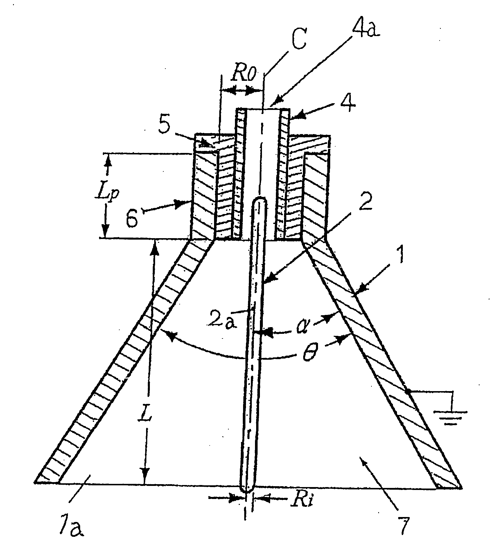
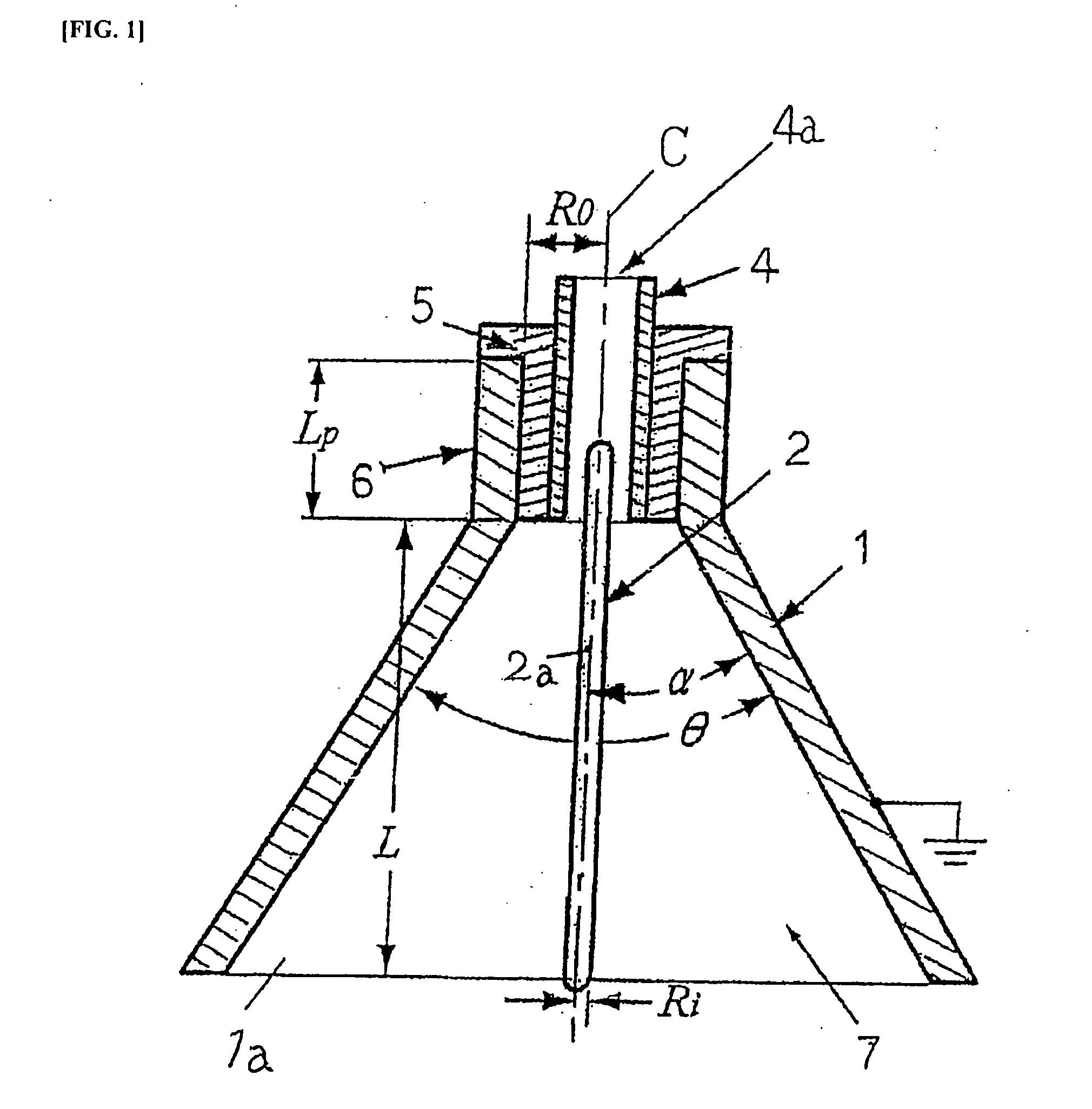
[0017]Also, the pumping pressure of the EHD pump can be increased, due to the fact that the EHD pump of this invention employs an electrode configuration in which a rod-shaped metal electrode is disposed along the central axis of a hollow conical metal electrode, instead of a prior art electrode configuration in which a linear internal electrode was disposed along the central axis of a cylindrical external electrode, and especially due to the fact that this invention employs a hollow conical metal electrode instead of a cylindrical external electrode as often used in the prior art. That is to say, in the case of a prior art electrode configuration described above, wherein a linear internal electrode was disposed along the central axis of a cylindrical external electrode, the linear internal electrode was parallel to the inner wall surface of the cylindrical external electrode, and the distance between the cylindrical external electrode and the linear internal electrode was uniform, on any surface in the central axial longitudinal direction of the linear internal electrode, and the electrical field between the cylindrical external electrode and the linear internal electrode was also uniform in the central axial longitudinal direction. Therefore, due to the fact that a heterocharge layer is formed uniformly across the entire surface of the linear internal electrode, the pressure in the direction of the center of the linear internal electrode which is applied to the operating fluid disposed between the cylindrical external electrode and the linear internal electrode is cancelled out by the entire surface of the linear internal electrode, and since a pressure differential arises in the central axial longitudinal direction, the pumping capacity is greatly reduced. By contrast, in this invention, the electrode configuration disposes a rod-shaped metal electrode along the central axis of a hollow conical metal electrode, and the pressure due to a heterocharge layer that forms on the surface of the rod-shaped metal electrode develops a gradient that decreases in the longitudinal direction toward the larger diameters of the hollow conical metal electrode. Consequently, the pressure differential in the electrode central axial direction is not cancelled out, and the more it is oriented toward the smaller diameters of the hollow conical metal electrode, the more it contributes to a stronger electric field and a greater pumping pressure.

Problems solved by technology

However, in such a prior art EHD pump, there was the drawback of increased channel resistance of the fluid channel formed within the pump, since bulky electrode groups had to be disposed within the pump, with the annular electrode 71 and the columnar electrode 72 staggered in the coaxial longitudinal direction and facing each other.
There was also the drawback that the cost of producing the electrode configuration was high, because of a structure in which the annular electrode 71 and the columnar electrode 72 are staggered in the coaxial longitudinal direction and facing each other.
Moreover, in this electrode configuration, there is a tendency to use larger electrodes, from the standpoint of electrode manufacture, so the cost of producing the electrode configuration becomes high.

Method used


Image

  • Electro hydro dynamics pump (EHD pump)
  • Electro hydro dynamics pump (EHD pump)
  • Electro hydro dynamics pump (EHD pump)

Examples


embodiment 1

Preferred Embodiment 1

[0031]FIG. 1 is a vertical sectional view of an EHD pump illustrating a basic working example of this invention. FIG. 1 shows a hollow conical metal electrode 1 formed from aluminum. At the top end of the hollow conical metal electrode 1 is formed a cylindrical neck 6, the top end part of which is open. Furthermore, the bottom end part 1a of the hollow conical metal electrode 1 is also open. Rod-shaped metal electrode 2 is stainless steel, the entire metal surface of which is exposed along the entire length thereof, forming an exposed metal part 2a. A fluid outflow duct 4 is installed in the neck 6 of the hollow conical metal electrode 1 through a plastic electrical insulation tube 5. In the preferred embodiment of FIG. 1, the fluid outflow duct 4 is formed from a glass tube with an outer diameter of 6 mm and an inner diameter of 4 mm, and forms a part of the fluid outflow channel, communicating with the inner part of the hollow conical metal electrode 1. Fluid...

embodiment 2

Preferred Embodiment 2

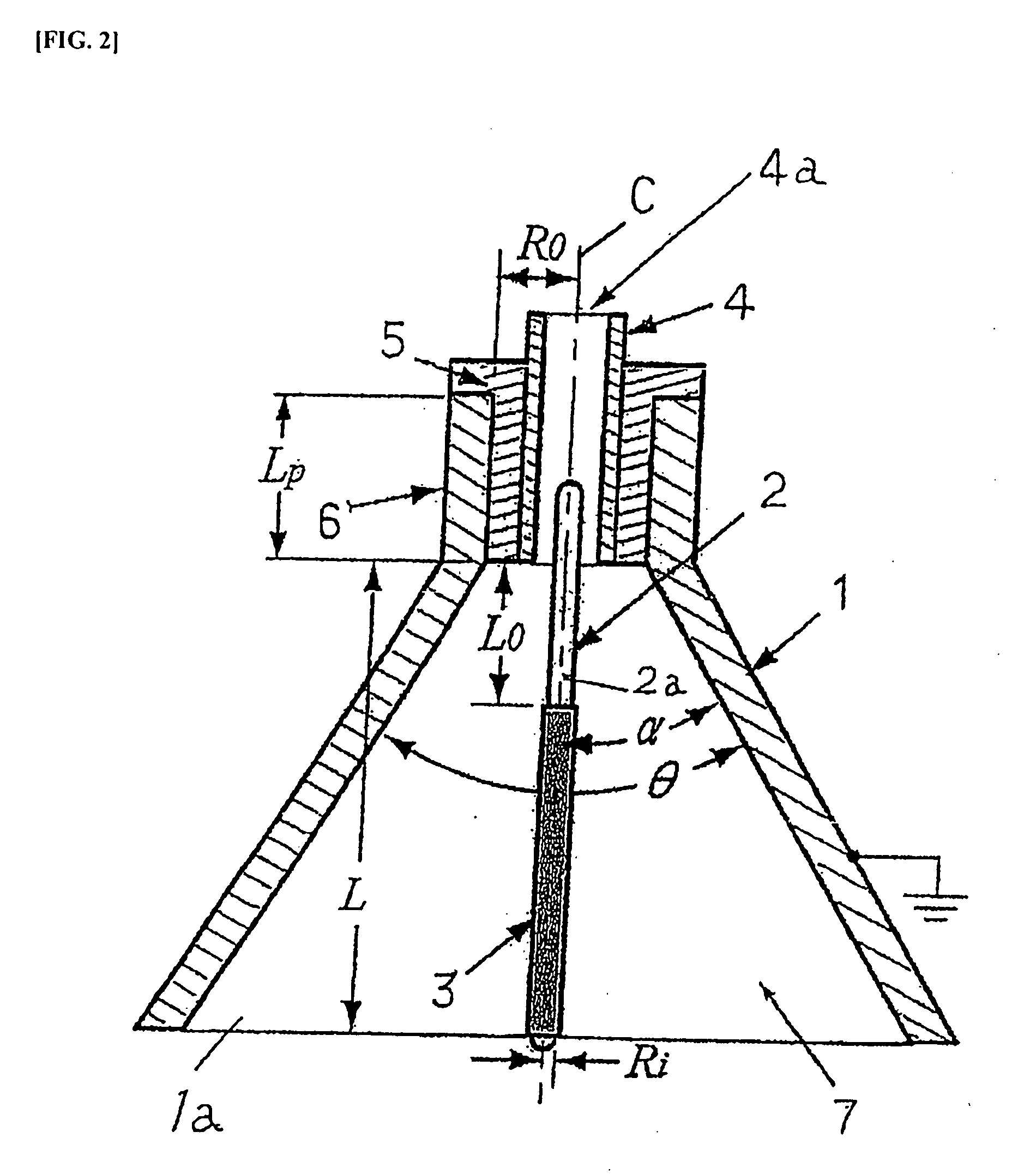
[0035]FIG. 2 illustrates another preferred embodiment of an EHD pump of this invention. In order to enhance pump characteristics, further improvements were made, using the EHD pump of FIG. 1 as a basis. The construction of the EHD pump of FIG. 2 is identical to that described in FIG. 1, except that the rod-shaped metal electrode 2 is removed. Also, the Reference Symbols (numerals and letters) given in FIG. 2 have the same meaning as in FIG. 1, except for the Reference Symbols “3” and “L0”.

[0036]That is to say, in the EHD pump shown in FIG. 2, a hollow conical metal electrode 1 open at the top end and at the bottom end 1a and a rod-shaped metal electrode are provided, and at the open top end of this hollow cylindrical metal electrode 1 is installed an electrically insulated fluid outflow duct 4 (fluid outflow channel) facing the hollow conical metal electrode 1, with the hollow conical metal electrode 1 and rod-shaped metal electrode 2 sharing a central axis C, ...

embodiment 3

Preferred Embodiment 3

[0040]In yet another preferred embodiment, FIG. 8 describes the results when two pump structures are concatenated, having the EHD pump structure as illustrated in FIGS. 1 and 2. The external dimensions per unit EHD pump structure were basically identical to those of preferred embodiment 1. However, as shown in FIG. 8, the length of the rod-shaped metal electrode 2′ was set at 75 mm, which is longer, and the rod-shaped metal electrode 2′ was disposed to hang across and pass through the two pump structures. Furthermore, the operating fluid was HFC 43-10 as above. When high voltage direct current of +16 kV was applied to the rod-shaped metal electrode 2′, and a fluid jet expelled from the first stage of the fluid outflow channel 4 was supplied to the second stage (upper part of the drawing) of the EHD pump structure, the pumping pressure PE in the second level fluid outflow channel 4 increases, and the maximum pumping pressure was about 5 kPa. However, the increas...


PUM


Abstract

To improve the configuration of electrodes disposed in the fluid channel of EHD pumps, and to reduce of the fluid channel of EHD pumps, as well as to reduce the cost of producing EHD pumps, and to increase the pumping pressure of EHD pumps. A hollow conical metal electrode open at the top end and the bottom end is used facing a rod-shaped metal electrode, and an electrically insulated fluid outflow channel is formed facing the hollow conical metal electrode, with the hollow conical metal electrode and rod-shaped metal electrode sharing a central axis, so that the two electrodes are disposed coaxially, and the rod-shaped metal electrode is disposed from the inner portion of the hollow conical metal electrode to the inner portion of the fluid outflow channel, and a portion of the rod-shaped metal electrode, positioned at the interface of at least the inner portion of the hollow conical metal electrode and the fluid outflow channel, serves as an exposed metal part, with this exposed metal part being caused to face the inner surface of the hollow conical metal electrode, and when an electric field is applied across the hollow conical metal electrode and the rod-shaped metal electrode, there is introduced a fluid wherein are formed dissociated ions, and high voltage direct current is applied across the hollow conical metal electrode and the rod-shaped metal electrode.

Description

[0001]This application claims priority under 35 U.S.C. § 119 to Japanese Patent Application No. JP2006-325678 filed Dec. 1, 2006, the entire content of which is hereby incorporated by reference.TECHNICAL FIELD[0002]This invention relates to an electrohydrodynamic pump (referred to as an “EHD pump”) which propels a fluid in which dissociated ions are formed, by the application of an electric field, within a fluid channel between a pair of electrodes to which high voltage direct current is applied, and in particular, this invention relates to the structure of the electrodes provided within an electrohydrodynamic pump, and the structure of a fluid channel within an electrohydrodynamic pump.DESCRIPTION OF THE RELATED ART[0003]In mechanical pumps that have been used for many years, which propel a fluid using rotary blades or reciprocating pistons, heat and noise were generated as a result of the friction and vibration accompanying the motion of these blades and pistons, and since mainten...

Claims


Application Information

Patent Timeline
IPC IPC(8): F04B37/00
CPCF04B19/006
Inventor HANAOKA, RYOICHITAKATA, SHINZOFUKAMI, TADASHI
Owner KANAZAWA INSTITUTE OF TECHNOLOGY
Learn More