Solution heat exchanger for absorption refrigerating machine

a technology of heat exchanger and absorption solution, which is applied in indirect heat exchangers, lighting and heating apparatuses, laminated elements, etc., can solve the problems of low temperature, crystallization of absorption solution used as working medium, and low temperatur

Inactive Publication Date: 2005-08-30
EBARA CORP
View PDF29 Cites 29 Cited by
  • Summary
  • Abstract
  • Description
  • Claims
  • Application Information

AI Technical Summary

Benefits of technology

[0014]The present invention has been made in view of the above drawbacks. It is therefore a first object of the present invention to provide a solution heat exchanger for an absorption refrigerating machine, which comprises a plate type heat exchanger and can stably be operated without crystallization even when the efficiency of the absorption refrigerating machine is greatly improved.
[0015]It is a second object of the present invention to provide a plate type heat exchanger which can be mass-produced at low cost with reduced size and weight, and can easily be changed in passage structure, and has a minimized pressure loss, and to provide a solution heat exchanger for an absorption refrigerating machine, which employs such a plate type heat exchanger.

Problems solved by technology

An absorption refrigerating machine has heretofore suffered a drawback in that an absorption solution used as working medium is crystallized when its concentration becomes high and its temperature becomes low.
Since the multitubular heat exchanger is used as the solution heat exchanger, and the solution heat exchangers installed independently of each other are connected to each other through pipes, the solution heat exchanger has the following drawbacks:① The amount of the solution in the heat exchangers and the pipes is large, and the start-up characteristics are poor.
② Since the solution heat exchanger is large in size and heavy, a reduction in size and weight is difficult to be carried out and is costly.③ The solution heat exchanger has complicated piping and requires a long time to be manufactured.④ The solution heat exchanger has a structure that cannot easily be mass-produced.
Therefore, the piping of the heat exchangers becomes complicated and costly.
Further, the space occupied by the heat exchangers cannot be reduced.

Method used


Image

  • Solution heat exchanger for absorption refrigerating machine
  • Solution heat exchanger for absorption refrigerating machine
  • Solution heat exchanger for absorption refrigerating machine

Examples


first embodiment

[0035]the present invention will be described below with reference to FIGS. 1 through 6.

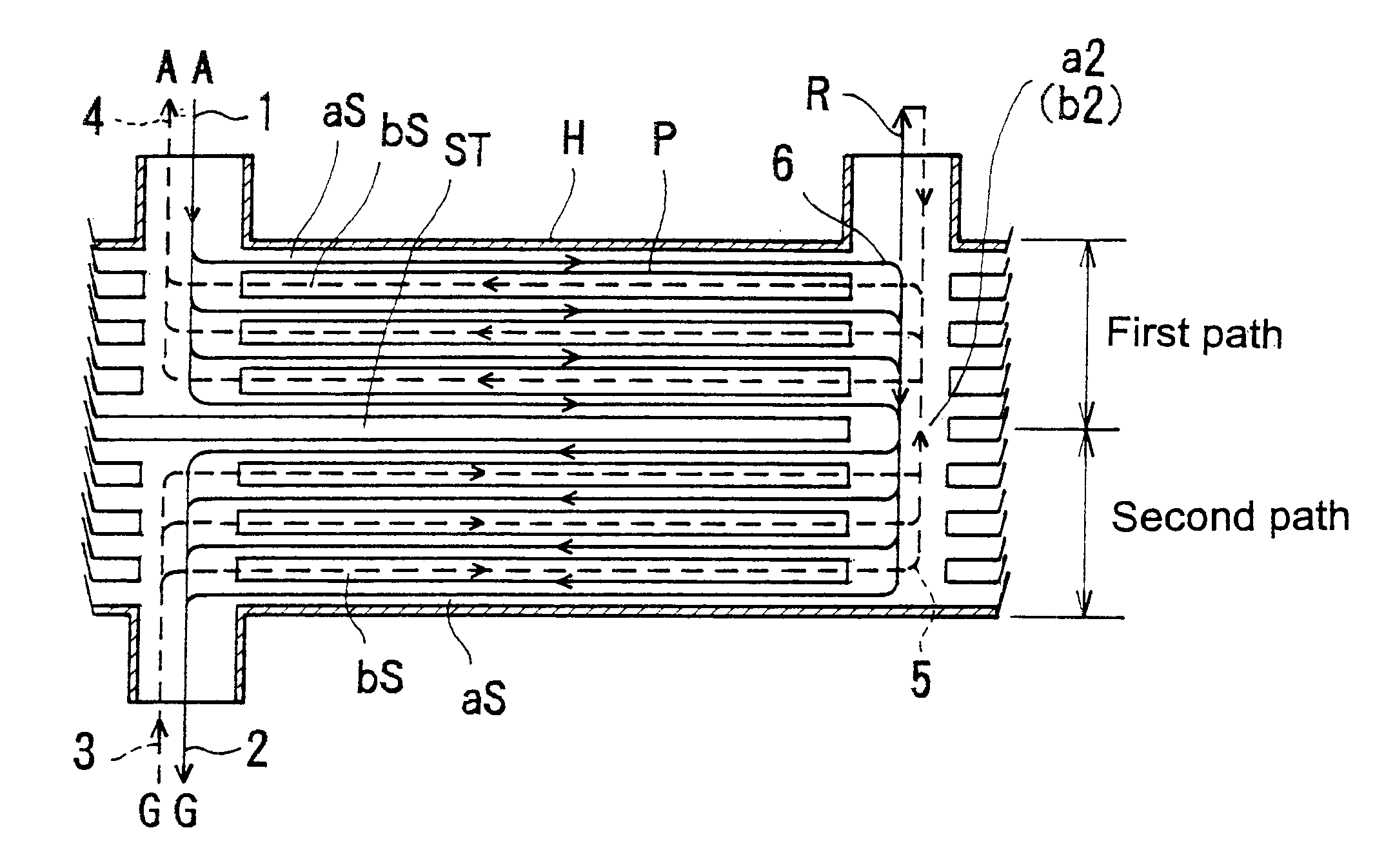
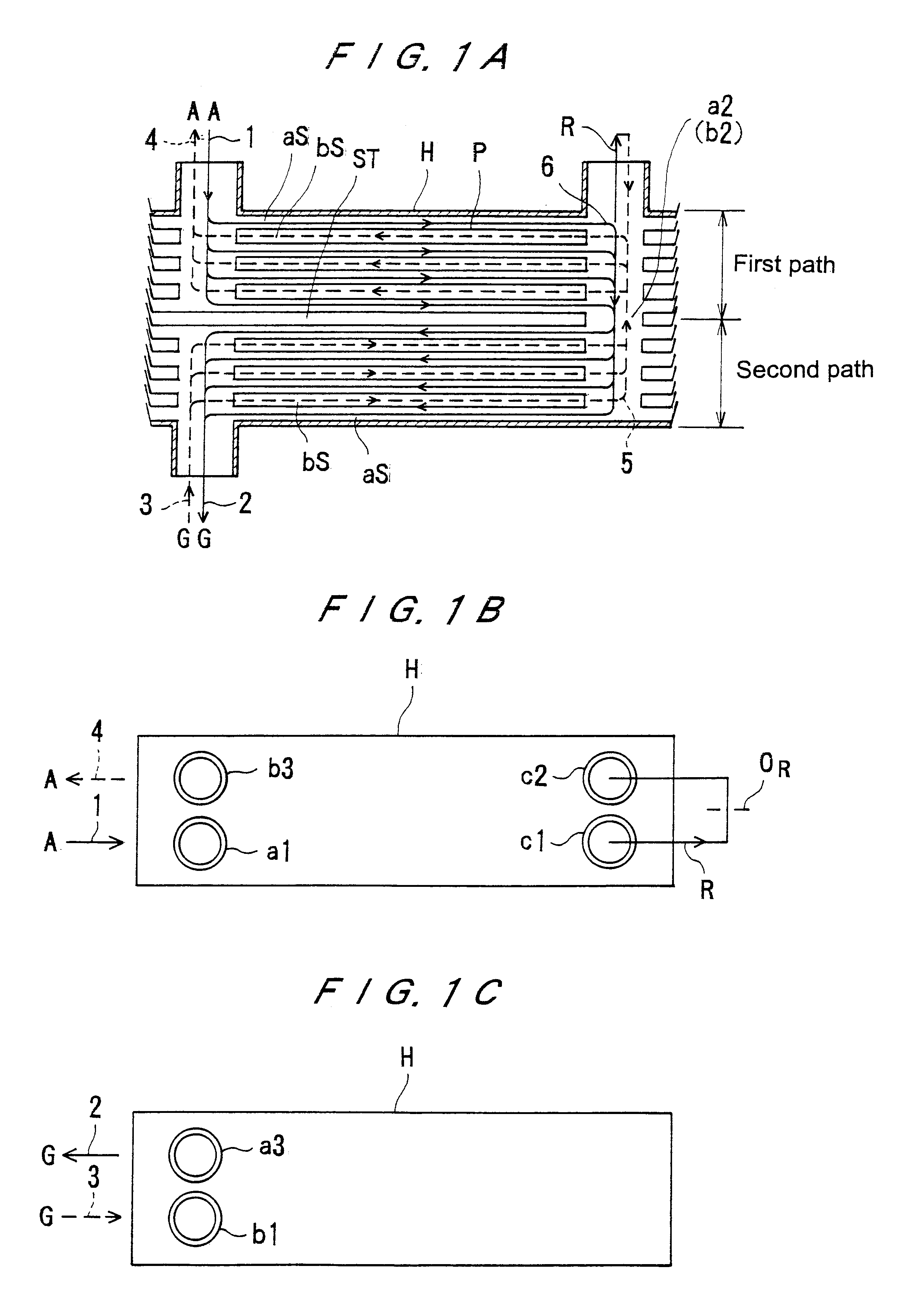
[0036]FIGS. 1A, 1B, and 1C are schematic views showing an example of a whole structure of a solution heat exchanger according to a first embodiment of the present invention. FIG. 1A is a cross-sectional front view of the solution heat exchanger, FIG. 1B is a plan view of the solution heat exchanger as viewed from above in FIG. 1A, and FIG. 1C is a plan view of the solution heat exchanger as viewed from below in FIG. 1A.

[0037]In FIGS. 1A through 1C, the reference character H denotes a solution heat exchanger, ST, a partition plate, and P, a plate. As indicated by the solid lines, a first, or dilute, solution 1 from an absorber A is introduced into the solution heat exchanger from a dilute solution inlet nozzle a1, and passed through inter-plate passages aS in a first path and an opening a2 formed in the partition plate ST. Then, the dilute solution 1 is passed through passages aS in a second path ...


PUM


Abstract

The present invention relates to a solution heat exchanger used for performing heat exchange between a dilute solution and a concentrated solution in a solution passage of an absorption refrigerating machine. The solution heat exchanger (H) comprises a plate type heat exchanger, and a communication portion (R) communicating between a dilute solution passage and a concentrated solution passage for introducing a portion of a dilute solution into a concentrated solution is provided in the solution heat exchanger (H).

Description

TECHNICAL FIELD[0001]The present invention relates to a heat exchanger, and more particularly to a plate type heat exchanger used for performing heat exchange between a dilute solution and a concentrated solution in a solution passage of an absorption refrigerating machine.BACKGROUND ART[0002]An absorption refrigerating machine has heretofore suffered a drawback in that an absorption solution used as working medium is crystallized when its concentration becomes high and its temperature becomes low. Therefore, an absorption refrigerating machine is designed with a margin for a crystallization line.[0003]Generally, in the absorption refrigerating machine, a region in which the absorption solution has a high concentration and a low temperature is an outlet for a concentrated solution in a solution heat exchanger. In order to increase the efficiency of the absorption refrigerating machine, it is necessary to lower the temperature of the concentrated solution at this outlet. Therefore, w...

Claims


Application Information

Patent Timeline
Patent Type & Authority Patents(United States)
IPC IPC(8): F25B15/02F28D9/00
CPCF25B15/02F28D9/005Y02B30/62Y02A30/27
Inventor INOUE, NAOYUKIMATSUBARA, TOSHIOTANAKA, SHOUJISUZUKI, AKIYOSHINAKAMURA, HIROKIUCHIMURA, TOMOYUKI
Owner EBARA CORP
Why Eureka
Try Eureka