Air drill

a technology of air drill and air plate, which is applied in the direction of portable power-driven tools, drilling machines, manufacturing tools, etc., can solve the problems of cracks leading to breakage, air drills falling on the floor, and body damage, so as to increase the strength of the bridge portion, increase the strength of the opening, and facilitate the effect of changing

Active Publication Date: 2005-08-30
SHINANO SEISAKUSHO
View PDF7 Cites 26 Cited by
  • Summary
  • Abstract
  • Description
  • Claims
  • Application Information

AI Technical Summary

Benefits of technology

[0012]The body preferably has a bridge portion located between the two openings. In this case, the strength of the openings is increased, and thus, the air drill is hardly broken even when the air drill falls on the floor.
[0013]The openings are preferably symmetrically positioned with respect to a rotor shaft of the air motor. Since this configuration enables the dim

Problems solved by technology

However, in the case where the conventional air drill is placed on a table or the like, if for some reason an air hose connected to the grip portion is pulled, the air drill may fall on the floor, and the body may be broken.
Since the air drill assumes a pistol-

Method used


Image

  • Air drill
  • Air drill
  • Air drill

Examples


Embodiment Construction

[0017]An embodiment of the present invention will be described with reference to the drawings.

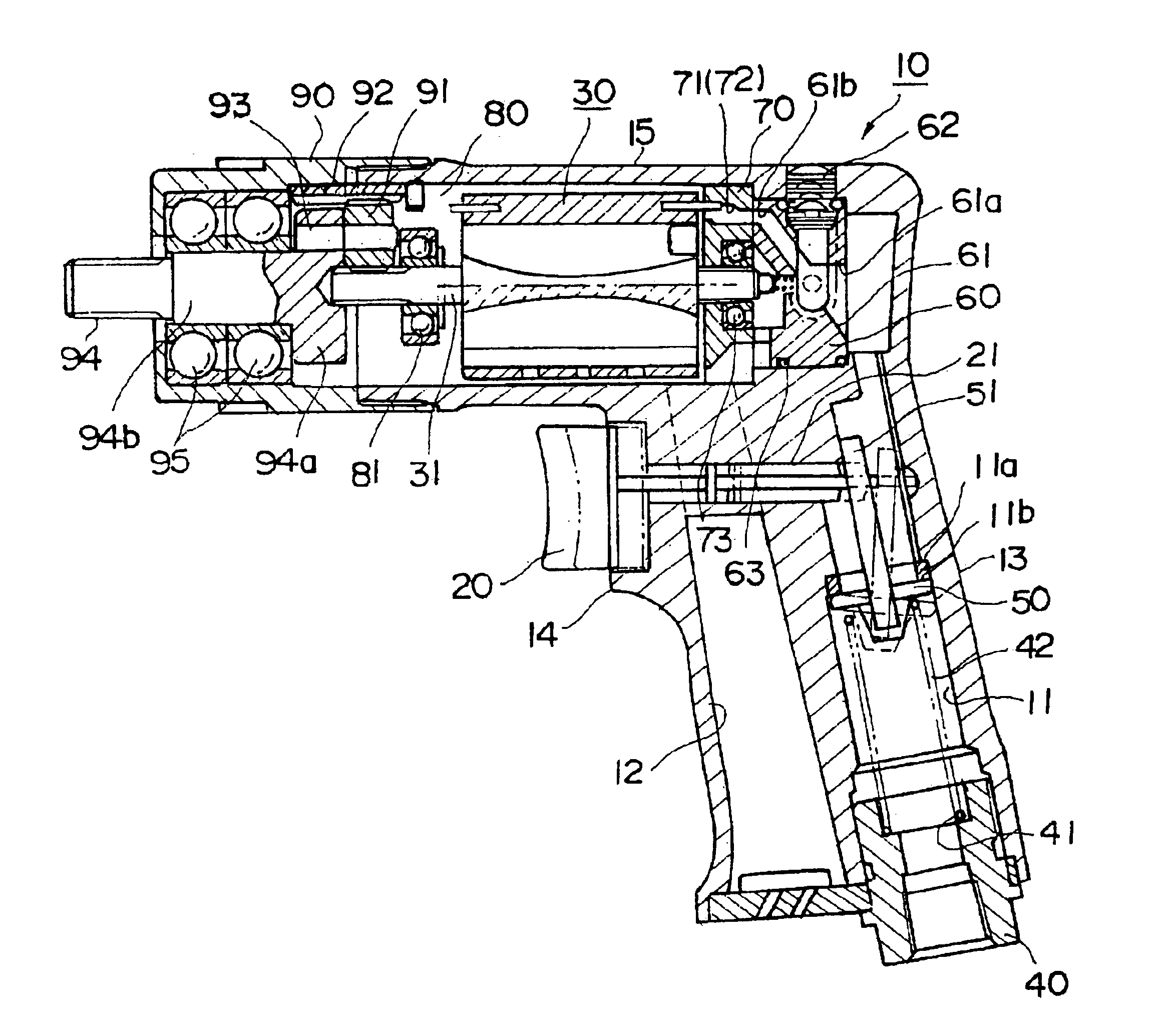
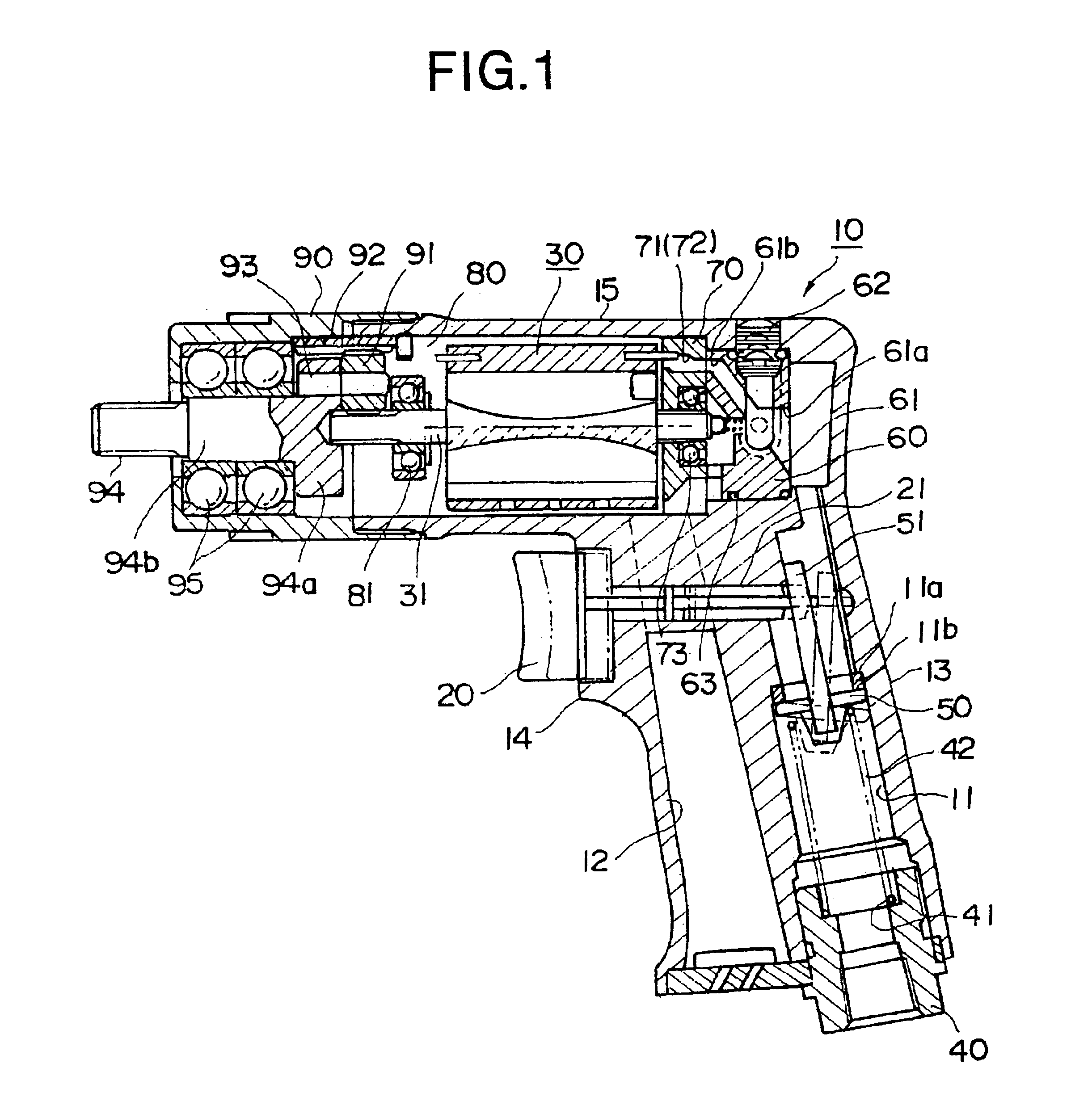
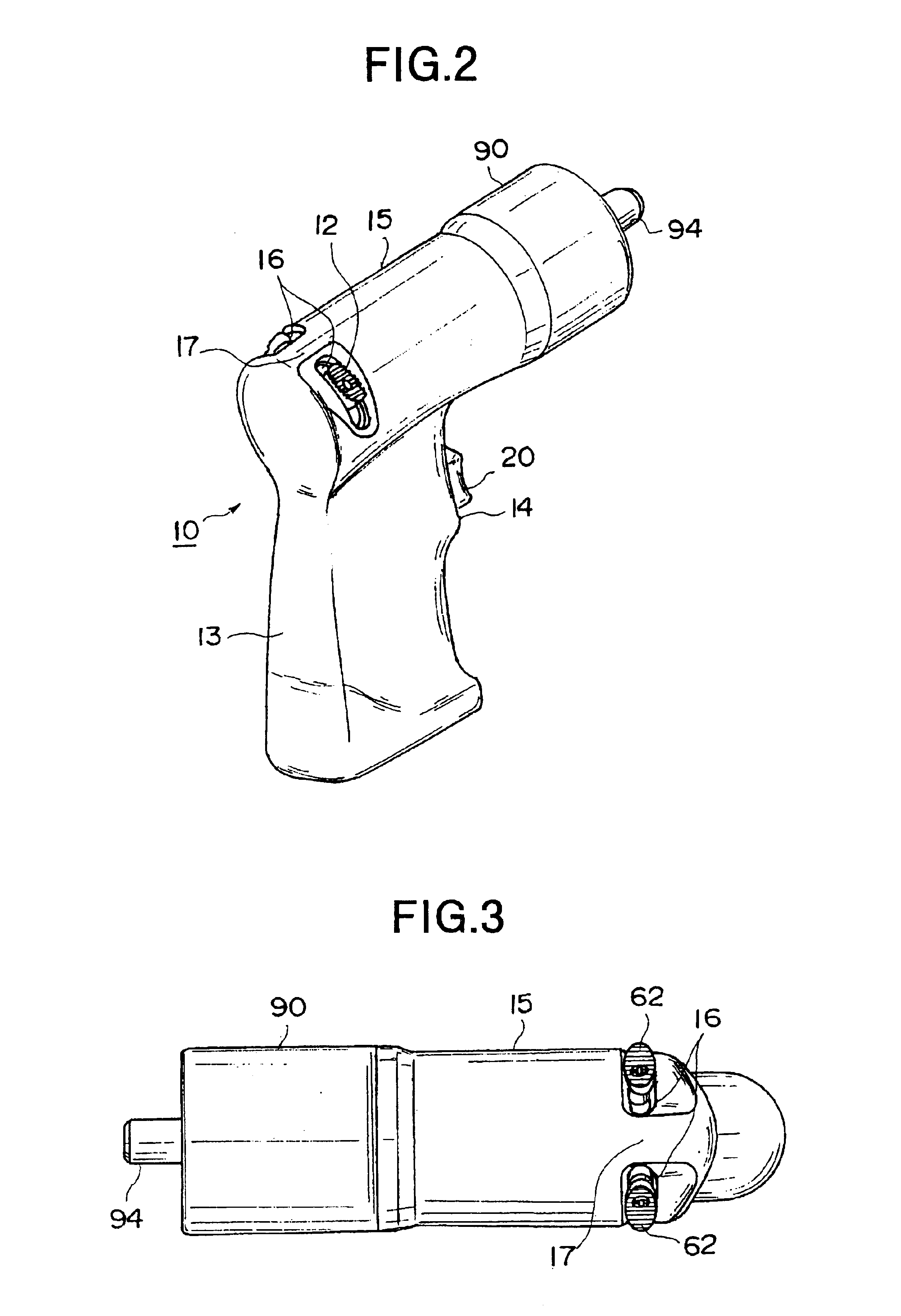
[0018]In FIG. 1, reference numeral 10 denotes a body of an air drill. The body 10 includes a grip portion 13 which has an air supply passage 11 and an air exhaust passage 12 formed therein; a trigger portion 14 which is formed above the grip portion 13 and supports a trigger 20; and a cylinder portion 15 which is formed above the trigger portion 14 and accommodates an air motor 30 therein.

[0019]A bushing 40 is fitted into the lower end of the air supply passage 11. A step 11a is formed at a middle portion of the air supply passage 11. A valve 50 seats on the step 11a via a valve seat 11b.

[0020]A valve spring 42 is disposed between the valve 50 and a receiving portion 41 which is formed in an upper portion of the bushing 40. Thus, the valve 50 is pushed against the valve seat 11b by means of the valve spring 42.

[0021]A pin 51 is affixed to the valve 50, and is connected to a connecting rod ...


PUM


Abstract

An air drill includes a body having a grip portion having an air supply passage and an air exhaust passage formed therein, a trigger portion formed above the grip portion and supporting a trigger, and a cylinder portion formed above the trigger portion and accommodating an air motor. A reverse valve is disposed within the cylinder portion in order to switch the direction of rotation of the air motor between forward and reverse directions. Two reverse levers are disposed in an upper portion of the reverse valve and slidably accommodated in two slit-shaped openings, respectively, which are formed in a grip-portion-side end of the cylinder portion.

Description

BACKGROUND OF THE INVENTION[0001]1. Field of the Invention[0002]The present invention relates to an air drill, and more particularly to a portable air drill capable of changing its rotational direction.[0003]2. Description of the Related Art[0004]A body of a conventional portable air drill capable of changing its rotational direction comprises a grip portion which has an air supply passage and an air exhaust passage formed therein; a trigger portion which is formed above the grip portion and supports a trigger; and a cylinder portion which is formed above the trigger portion and accommodates an air motor therein.[0005]A lock ring is threadingly engaged with an open end of the cylinder portion. A spindle is disposed inside the lock ring via bearings. A reverse valve is disposed within a closed end portion of the cylinder portion, opposite the open end thereof.[0006]The reverse valve has a single reverse lever. Rotational direction of the air motor can be reversed through switching th...

Claims


Application Information

Patent Timeline
IPC IPC(8): B25F5/00B25F5/02
CPCB25F5/00
Inventor IZUMISAWA, NOBUYUKI
Owner SHINANO SEISAKUSHO
Why Eureka
Try Eureka